
Stepwise advancement of a medical tool

Inactive Publication Date: 2009-12-10
SYNC RX
View PDF102 Cites 62 Cited by
  • Summary
  • Abstract
  • Description
  • Claims
  • Application Information

AI Technical Summary

Benefits of technology

[0027]It is hypothesized by the inventors that embodiments of the current invention offer measures for reducing the aforementioned risk of a guide wire being advanced in an undesirable direction. For example, embodiments of the current invention may reduce the aforementioned risk of a guide wire being advanced into the wall of a blood vessel and creating a perforation or a dissection of that wall. It is also hypothesized by the inventors that advancing a guide wire in the synchronized manner described herein will, in some cases, improve the efficacy of the guide wire in penetrating an occlusion. Separately, it is also hypothesized by the inventors that advancing a guide wire in the synchronized manner described herein will, in some cases, facilitate inserting the guide wire into a side branch, the angle of which, relative to the main lumen, varies in the course of the vessel's motion cycle.
[0028]In an embodiment, the guide wire is advanced within a coronary vessel in a stepwise manner, only at a selected phase of the cardiac cycle. In an embodiment, the selected phase of the cardiac cycle is a diastolic or end-diastolic phase, when the blood vessels are relatively further spread apart and less twisted. Compared to unsynchronized advancement of the guide wire (for example, continuous advancement of the guide wire throughout the cardiac cycle), synchronized stepwise advancement in a diastolic or end-diastolic phase typically results in the guide wire being advanced, during a greater portion of its forward motion, along the vessel and, during a lesser portion of its forward motion, towards the wall of the vessel. That, in turn, typically reduces the likelihood of the guide wire perforating or dissecting the vessel wall, and typically increases the efficacy of the guide wire penetrating a possible occlusion in the vessel.

Problems solved by technology

When a guide wire is used for penetrating an occlusion within an artery that changes its shape as a result of organ motion, it may result in (a) the guide wire being pushed along the artery, at some phases of the motion cycle, but (b) in an undesirable direction, for example, toward the wall of the artery, at other phases of the motion cycle.
In some cases, the ability to penetrate the occlusion with the guide wire is therefore hindered.
In other cases, advancement of the guide wire towards the wall of the artery results in a perforation or dissection of the artery's wall.
Such perforation or dissection typically creates some amount of clinical risk.

Method used


Image

  • Stepwise advancement of a medical tool
  • Stepwise advancement of a medical tool
  • Stepwise advancement of a medical tool

Examples


Embodiment Construction

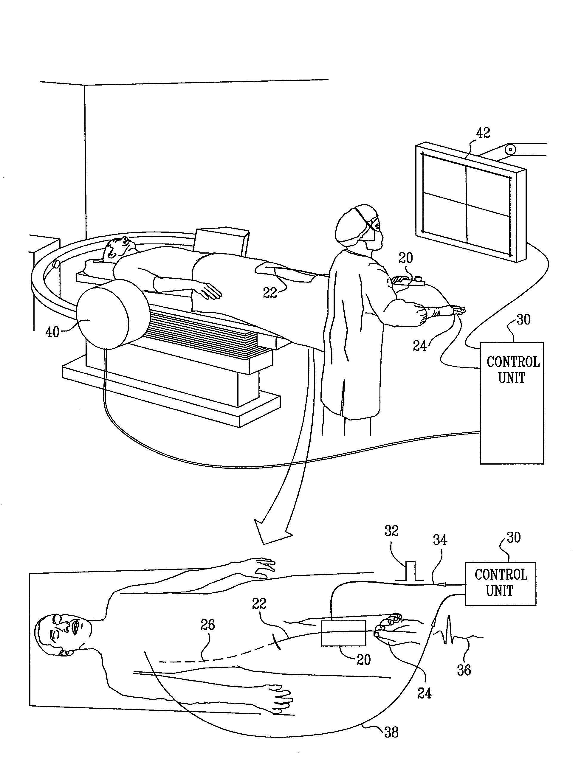
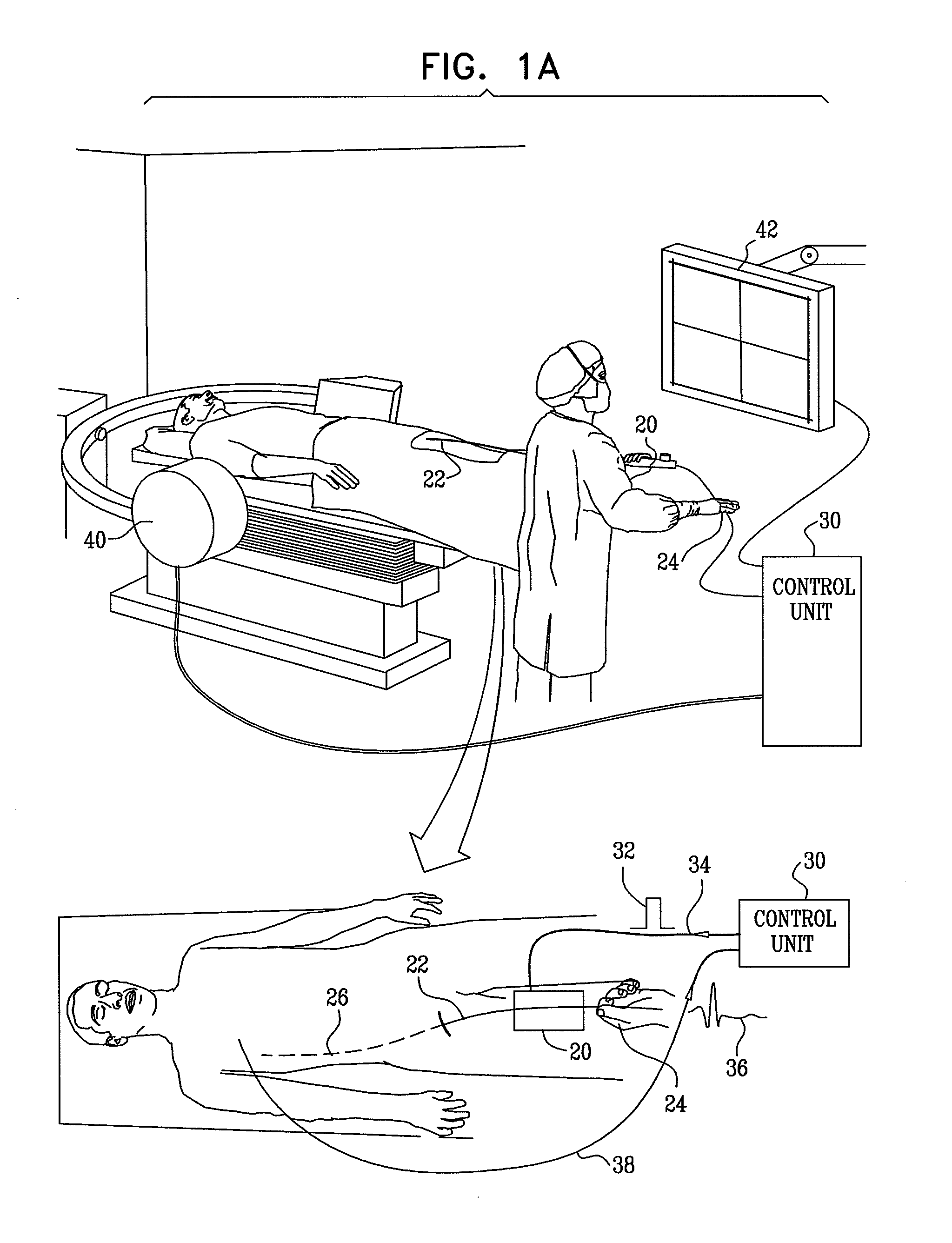
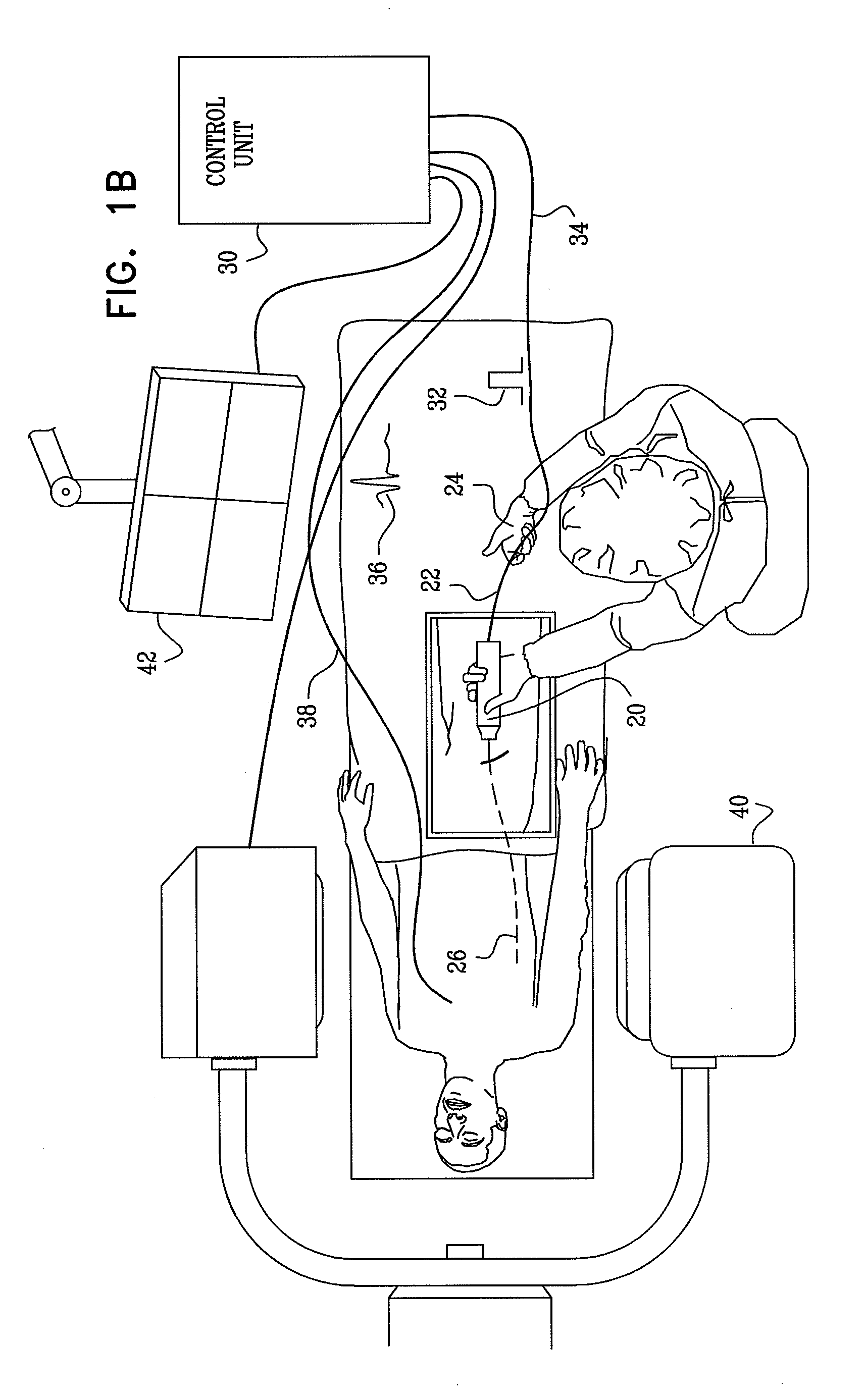
[0088]Reference is now made to FIGS. 1A and 1B, which are schematic illustrations of respective views of a guide wire motion modulator 20 being used by a physician, in accordance with an embodiment of the invention. In an embodiment, a tool such as a guide wire 22 is advanced by the physician's hand 24 within arterial system 26 of the patient. The actual forward motion of guide wire 22 is modulated by guide wire motion modulator 20. Guide wire motion modulator 20 receives, from control unit 30, a synchronization signal 32 over a line 34. Control unit 30 derives synchronization signal 32 from an ECG signal 36 of the patient, which is received via a line 38. In an embodiment, the guide wire motion modulator is used for advancing a coronary guide wire. Images of the advancement of guide wire 22 within arterial system 26 of the patient are typically generated by a fluoroscopy system 40 and displayed on a monitor 42. In some embodiments, guide wire 22 is inserted into arterial system 26 ...


PUM


Abstract

Apparatus is provided, including a sensor for sensing a phase of cyclic activity of a subject's body system. A tool modulator includes a gate configured:in a first cycle of the cyclic activity, to allow movement of a tool, in response to the cyclic activity being at a first given phase thereof,following the given phase in the first cycle and prior to an occurrence of the given phase in a subsequent cycle of the cyclic activity, to inhibit the movement of the tool, andin a second cycle of the cyclic activity, subsequent to the inhibiting of the movement, to allow movement of the tool, in response to the second cycle of the cyclic activity being at the given phase thereof.An accumulation facilitator facilitates an accumulation of the tool in the tool modulator, and / or an accumulation of energy in the tool.

Description

CROSS-REFERENCES TO RELATED APPLICATIONS[0001]The present patent application claims priority of U.S. Provisional Patent Application No. 61 / 129,331 to Iddan, filed on Jun. 19, 2008, entitled “Stepwise advancement of a medical tool,” and is a continuation-in-part of:[0002](a) PCT Application PCT / IL2008 / 000316 to Iddan, filed on Mar. 9, 2008, entitled “Imaging and tools for use with moving organs,”[0003](b) U.S. patent application Ser. No. 12 / 075,244 to Tolkowsky, filed Mar. 10, 2008, entitled “Imaging for use with moving organs,”[0004](c) U.S. patent application Ser. No. 12 / 075,214 to Iddan, filed Mar. 10, 2008, entitled “Tools for use with moving organs,” and[0005](d) U.S. patent application Ser. No. 12 / 075,252 to Iddan, filed Mar. 10, 2008, entitled “Imaging and tools for use with moving organs,”[0006]all of which claim the benefit of U.S. Provisional Patent Application Nos.:[0007]60 / 906,091 filed on Mar. 8, 2007,[0008]60 / 924,609 filed on May 22, 2007,[0009]60 / 929,165 filed on Jun. ...

Claims


Application Information

Patent Timeline
IPC IPC(8): A61M25/09A61F2/958
CPCA61B6/503A61B6/5217A61B6/541A61B2017/00252A61B2017/00694A61B2017/00703A61B8/02A61B2017/22094A61F2/958A61F2002/9517A61M25/09041A61M2025/09116A61B5/06A61B2017/22044G16H50/30A61F2/9517
Inventor IDDAN, GAVRIELTOLKOWSKY, DAVIDCOHEN, RANBLANK, JACOB
Owner SYNC RX
Learn More