
Printed substrate, method for manufacturing floor panels and method for manufacturing printed substrates

Inactive Publication Date: 2009-12-10
FLOORING IND LTD
View PDF4 Cites 14 Cited by
  • Summary
  • Abstract
  • Description
  • Claims
  • Application Information

AI Technical Summary

Benefits of technology

[0012]Due to the fact that the printed decors are grouped according to their tint, a smoother division of the printed substrate in the separate printed decors becomes possible, whereas still a full-value plank effect is maintained. Preferably, the printed decors of two or more floor panels are obtained from a single stripe, wherein dividing the print into these two or more printed decors then can be performed in a less accurate manner. Moreover, the stripe can be divided at choice into several formats of printed decors, such that it will also be profitable in the logistic range in respect to the amount of printed substrates that must be kept in stock. The respective printed decors may be obtained from portions of the stripe concerned located next to each other as well as located after one another. Such arrangement in groups for performing the print also allows a simpler printing process. The aforementioned tint can be obtained, for example, by means of a fond print performed in stripes on the respective substrate, over which a motif print is applied.
[0019]Preferably, the print of the stripes is constructed of a uniform or virtually uniform background color or fond print and a motif or motif print preferably repeating itself in length direction. Such a print allows for a simple manufacture of the printed substrate.

Problems solved by technology

Further, it is known to apply a continuous gradual tint modification in the print of printed substrates over the entire width of the substrate, which results in a rather limited increase of the color-richness in a floor covering composed on the basis of floor panels with such printed decors, wherein, however, an accurate division of the printed substrate is not required.
A disadvantage of such printed substrates, however, is that in the printed decor of each floor panel a continuous gradual tint modification is present, which can result in an unnatural appearance.

Method used


Image

  • Printed substrate, method for manufacturing floor panels and method for manufacturing printed substrates
  • Printed substrate, method for manufacturing floor panels and method for manufacturing printed substrates
  • Printed substrate, method for manufacturing floor panels and method for manufacturing printed substrates

Examples


Embodiment Construction

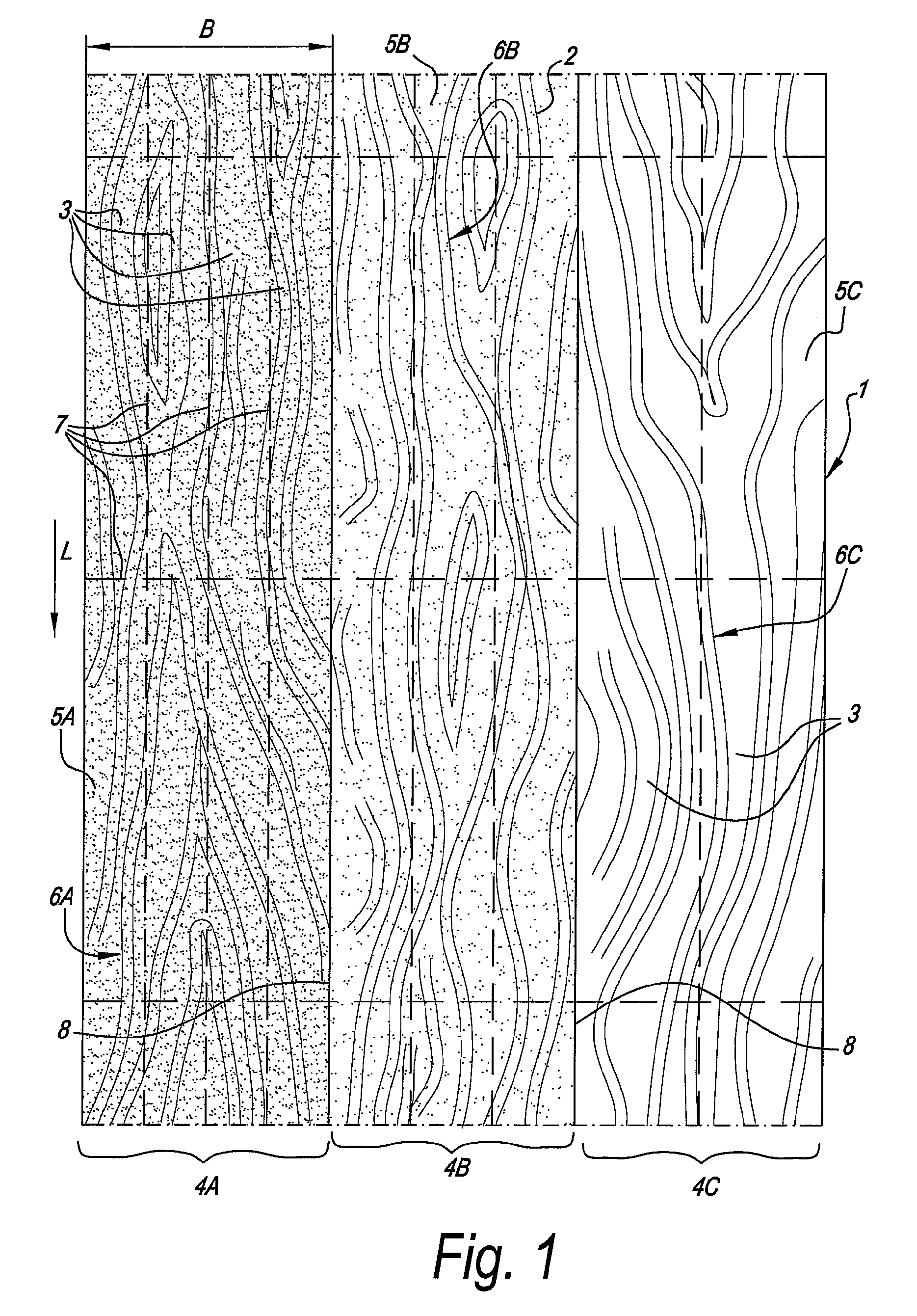
[0035]FIG. 1 illustrates a printed substrate 1, which can be applied when manufacturing floor panels. The printed substrate 1 includes a print 2 in which the printed decors 3 of a plurality of floor panels are grouped in stripes 4A-4B-4C of similar or approximately equal tint. In this example, the printed substrate 1 includes three stripes 4A-4B-4C of different tint, all of the stripes having approximately the same width B. The stripes 4A-4B-4C extend with their longitudinal direction in the longitudinal direction L of the substrate 1.

[0036]It will be appreciated that the number of stripes in a given substrate is not limited. The width B of each of the stripes 4A-4B-4C approximately corresponds to the width of one or more floor panels, and preferably to the width of at least two floor panels. Of course, material to be removed when dividing the printed substrate 1 and further finishing the floor panels can be taken into account here. Preferably, the printed substrate 1 comprises at l...


PUM

PropertyMeasurementUnit
Flexibilityaaaaaaaaaa
Widthaaaaaaaaaa

Abstract

A printed substrate may be used for manufacturing floor panels that have at least a basic panel and provided thereon a top layer with a printed decor. The printed substrate may include a print. The print may include the printed decors of a plurality of the floor panels. The printed decors in the print may be grouped in stripes of similar tint.

Description

PRIORITY STATEMENT[0001]This US non-provisional application claims priority under 35 USC §119 to Belgian Patent Application No. 2008 / 0318 filed Jun. 10, 2008, the content of which is incorporated herein in its entirety by reference.BACKGROUND[0002]1. Field of the Invention[0003]In general, the invention relates to printed substrates, a method for manufacturing floor panels on the basis of such printed substrates, as well as to a method for manufacturing such printed substrates.[0004]More particularly, the invention relates to a printed substrate for manufacturing floor panels of the type having at least a basic panel and a top layer with a printed decor provided on the basic panel. The print of the printed substrate includes the printed decors of a plurality of floor panels.[0005]For example, the printed substrates may be applied for manufacturing floor panels substantially consisting of a MDF or HDF (Medium or High Density Fiberboard) basic panel and a top layer provided thereon, s...

Claims


Application Information

Patent Timeline
IPC IPC(8): B32B3/02B32B37/10
CPCB44C5/0446B44C5/0469Y10T428/24802E04F2201/0153Y10T156/1052B44F1/08
Inventor MEERSSEMAN, LAURENTNOLLET, OKE
Owner FLOORING IND LTD
Learn More