Voice coil device and speaker device using the voice coil device

a voice coil and voice coil technology, which is applied in the direction of transducer details, electrical transducers, electrical equipment, etc., can solve the problems of high frequency band limit frequency fh, coil bobbin or voice coil problematically colliding with the frame, and large vibration of voice coil bobbin and voice coil

Inactive Publication Date: 2009-12-10
PIONEER CORP +1
View PDF8 Cites 3 Cited by
  • Summary
  • Abstract
  • Description
  • Claims
  • Application Information

AI Technical Summary

Benefits of technology

[0019]The present invention has been achieved in order to solve the above problems. It is an object of this invention to provide a voice coil device and a speaker device using the voice coil device capable of preventing a lead wire of a voice coil from cutting at the time of driving of the voice coil device.
[0020]It is another object of this invention to provide a speaker device capable of preventing the voice coil bobbin from colliding with a magnetic circuit and suppressing an unnecessary high-frequency component (peak) around high-frequency-band limit frequency Fh. In addition, it is still another object of this invention to provide a speaker device capable of preventing an adhesive from flowing to a neck side of the diaphragm at the time of mounting a buffer member (including a dustproof function) onto a diaphragm.
[0021]Further, it is still another object of this invention to improve a weight balance by arranging the magnetic circuit on a sound output side (front side) of the diaphragm, thereby to suppress transmission of unnecessary vibration to a speaker mounting portion of a vehicle and occurrence of an abnormal sound from the speaker mounting portion and to make a protruding dimension of the speaker device from the speaker mounting portion to the sound output side as small as possible.

Problems solved by technology

Therefore, there is a problem that in some drawing states of the lead wire, tinsel stress and bending stress repeatedly operate on a drawn portion from the wound member of the lead wire in accordance with the driving of the speaker device, and hence the lead wire is cut at a bent and folded portion thereof.
Therefore, in such a speaker device, at the time of excessive input to the voice coil, the voice coil bobbin and the voice coil vibrate with large magnitude.
Thereby, the voice coil bobbin or the voice coil problematically collides with the frame and the magnetic circuit.
In addition, in the speaker device of the front magnetic circuit system using the cone-shape diaphragm formed into the above-mentioned straight shape, there is a problem that high-frequency-band limit frequency Fh is generally high and hence an unnecessary high-frequency component (peak) occurs thereabout.
However, in such a speaker device, since the magnetic circuit is provided on the front side of the diaphragm, the diaphragm cannot be curved to project to the sound output side without a restriction.
Namely, when the cone-shape diaphragm formed into the paracurved shape is used for such a speaker device, it is problematic that since an inner peripheral portion (neck) of the diaphragm is curved to project to the side of the magnetic circuit, a space between the diaphragm and the magnetic circuit becomes small and hence a magnitude margin (magnitude width) of vibration of the diaphragm becomes small.
However, in such a speaker device, when the dustproof cushion is mounted onto the neck (inclined surface) of the diaphragm by an adhesive, the adhesive problematically flows onto the neck side of the diaphragm at the time of mounting the dustproof cushion.
Hence, at the time of the driving of the on-vehicle speaker device, the vibration by the diaphragm is transmitted to the mounting portion of the vehicle via the frame, and thus an abnormal sound problematically occurs from the mounted portion.

Method used


Image

  • Voice coil device and speaker device using the voice coil device
  • Voice coil device and speaker device using the voice coil device
  • Voice coil device and speaker device using the voice coil device

Examples


first embodiment

(Entire Configuration of Speaker Device)

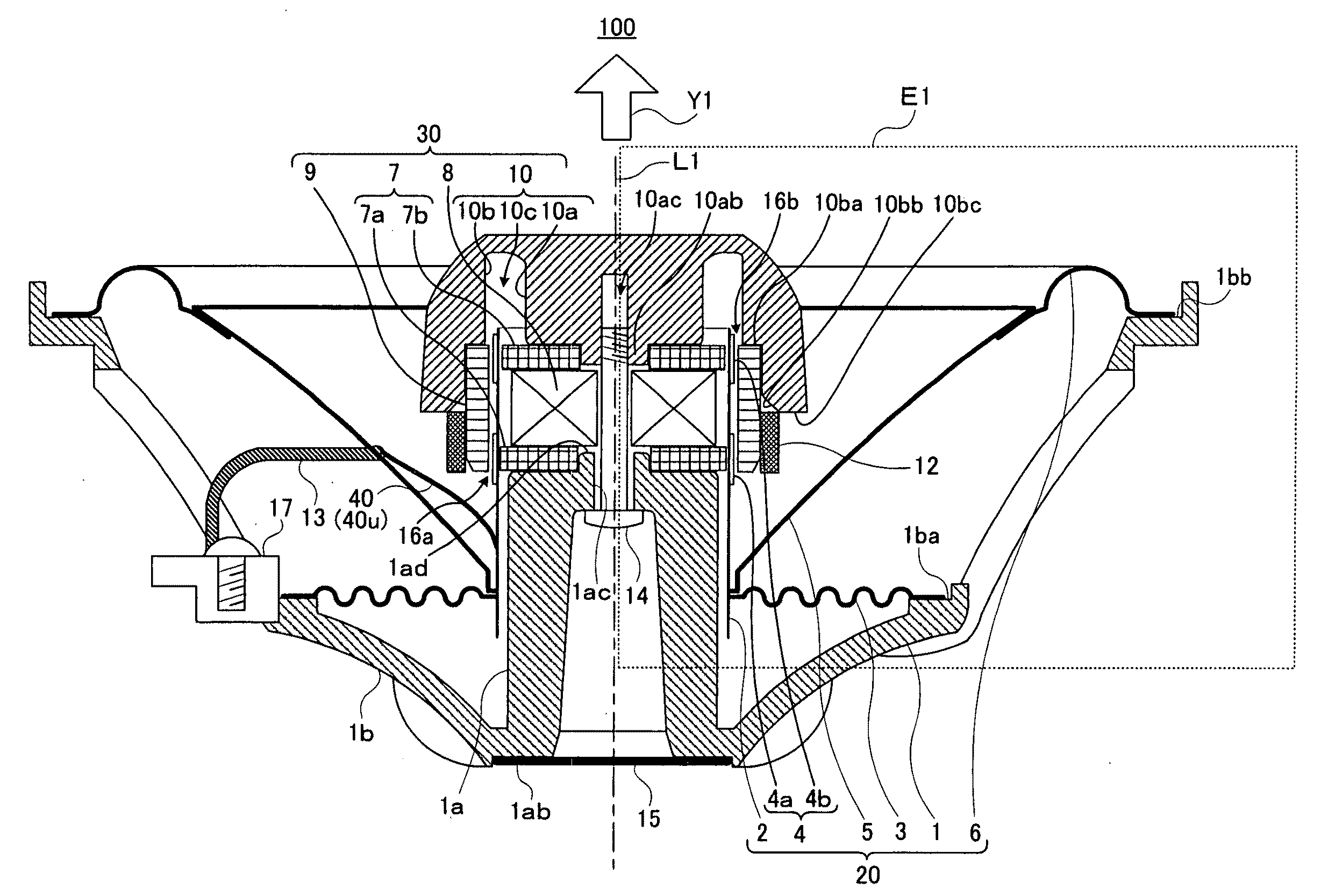
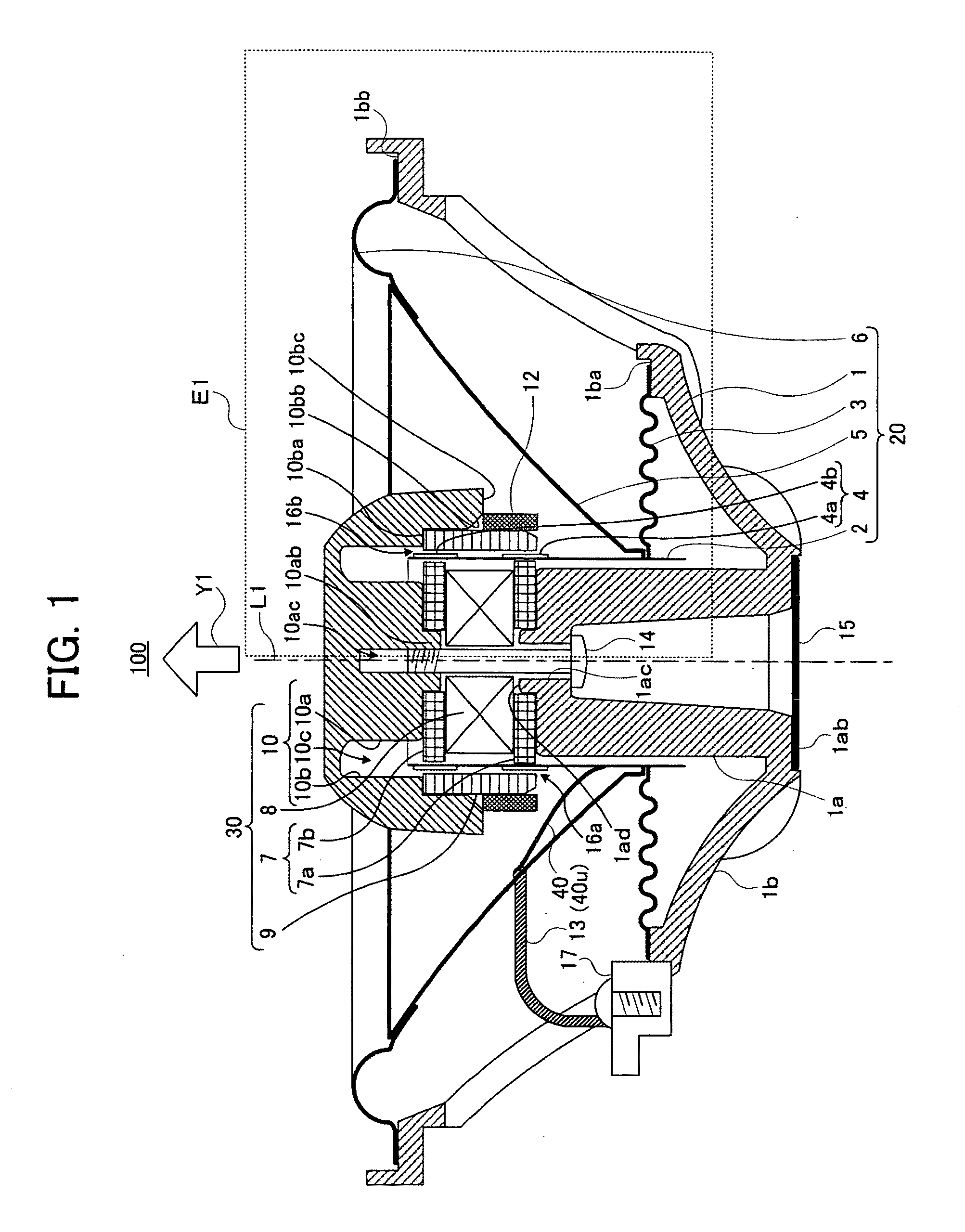
[0066]In this embodiment, the speaker device of the front magnetic circuit system includes the plural magnetic gaps and voice coils, respectively. Thereby, it is intended to prevent collision of the voice coil bobbin and the magnetic circuit. Also, in this embodiment, there is provided a structure of the voice coil device in the speaker device, particularly, a bending and folding structure of the lead wire capable of preventing the cutting of the lead wire of the voice coil.

[0067]FIG. 1 schematically shows a configuration of a speaker device 100 according to the embodiment of the present invention. The speaker device 100 can be preferably used as an on-vehicle speaker. FIG. 1 shows a cross-sectional view when cutting the speaker device 100 by a plane including a central axis L1 thereof. The description will be given of the configuration of the speaker device 100 of this embodiment, below.

[0068]As shown in FIG. 1, the speaker device 100 mainly ...

second embodiment

[0120]Similarly to the first embodiment, in a second embodiment, plural magnetic gaps and voice coils are provided in the speaker device of the front magnetic circuit system so that collision of the voice coil bobbin and the magnetic circuit is prevented. Additionally, in the second embodiment, the step portion having the upper surface on which flatness is ensured is provided on the inner peripheral portion (neck portion) of the diaphragm. Thereby, the unnecessary high-frequency component (peak) around the high-frequency-band limit frequency Fh can be suppressed, and attachment work of the buffer member having the buffer function and the dustproof function can be easier.

[0121]Next, the description will be given of a configuration of a speaker device 200 according to the second embodiment with reference to FIG. 5 and FIG. 6. The same reference numerals are given to the same components as those of the speaker device 100 of the first embodiment, the explanation of which will be omitted...

third embodiment

[0140]This embodiment is related to a mounting method of the speaker device. In summary, in this embodiment, in view of the whole weight balance of the speaker device, the magnetic circuit system having the large weight compared with other components of the speaker device is arranged on the front side (sound output side) of the diaphragm, and the gravity of the speaker device is set to the sound output side (front side) of the diaphragm. Then, at the mounting portion of the frame positioned on the plan surface including the gravity, the speaker device is mounted on the mounted portion. Thereby, the distance (projecting dimension) that the component of the speaker device projects on the sound output side of the diaphragm with respect to the speaker mounting portion becomes as small as possible. Moreover, at the time of the driving of the speaker device, it is suppressed that the unnecessary vibration is transmitted to the speaker mounting portion, and it is prevented that the abnorma...


PUM


Abstract

An example speaker device includes a vibration system having a frame, first and second voice coils, a voice coil bobbin, a diaphragm and a magnetic circuit holder, and a magnetic circuit system having a yoke, a magnet and first and second plates. The first and second voice coils are wound around the voice coil bobbin with a constant space. The diaphragm has a step portion having an upper surface ensuring flatness at an inner peripheral portion (neck) thereof. An inner peripheral edge portion of the diaphragm is fixed to the voice coil bobbin. The first plate, the magnet and the second plate are fixed onto a pole portion of the frame in an upward order, respectively. The annular yoke is mounted onto a predetermined position of the magnetic circuit holder formed into a mushroom shape, and the magnetic circuit holder is fixed onto the second plate via a bolt. Thereby, the first and second magnetic gaps are formed in the vicinity of the first and second voice coils, respectively.

Description

CROSS REFERENCE TO RELATED APPLICATION[0001]This application is a divisional of application Ser. No. 11 / 274,277, filed Nov. 16, 2005, the contents of which are incorporated herein in their entirety.BACKGROUND[0002]1. Field of the Invention[0003]The present invention relates to structures of a voice coil device and a magnetic circuit for a speaker device, and a mounting method of the speaker device.[0004]2. Description of Related Art[0005]Conventionally, there is known a speaker device including a vibration system having a diaphragm and a voice coil device having a voice coil bobbin, a voice coil wound around the voice coil bobbin and a wound member (e.g., a tape or a belt paper) attached to the voice coil bobbin, and a magnetic circuit having a yoke, a magnet and a plate. The magnetic circuit is arranged on a rear side of the diaphragm.[0006]As the voice coil device of this kind, there is known a voice coil bobbin having a bobbin around which the voice coil is wound and a reinforcem...

Claims


Application Information

Patent Timeline
Patent Type & Authority Applications(United States)
IPC IPC(8): H04R1/00
CPCH04R1/26
Inventor ABE, YASUHISAKUDO, YOSHIMI
Owner PIONEER CORP
Why Eureka
Try Eureka