Eureka AIR delivers breakthrough ideas for toughest innovation challenges, trusted by R&D personnel around the world.

Zones for wireless networks with relays

a wireless network and relay technology, applied in the field of wireless communications, can solve the problems of limited data rate and gaps in coverage of the given cell, increased system complexity, spectrum efficiency penalty, etc., and achieve the effect of improving detection performan

Active Publication Date: 2009-12-10
APPLE INC
View PDF15 Cites 254 Cited by
  • Summary
  • Abstract
  • Description
  • Claims
  • Application Information

AI Technical Summary

Benefits of technology

[0045]According to an aspect of the invention, there is provided a method of facilitating intra-cell peer-to-peer communication comprising: maintaining a destination address table for a BS that includes destination addresses that are served by the BS; upon receiving a packet containing a destination address, determining if the destination address is in the address table or not; if the destination address is within the table, routing the packet towards the destination without upper layer processing, and otherwise routing the packet for upper layer processing.
[0064]In some embodiments, the method further comprises defining for mobile relay stations a system reserved sub-set of PN indexes so as to avoid collisions when a MRS moves across the network.
[0115]In some embodiments, the method further comprises performing interference cancellation techniques to improve detection performance.

Problems solved by technology

One drawback of such wireless networks is that MSs near an edge of the given cell suffer performance loss due to interference from other cells in cellular networks and propagation loss in non-cellular networks which results in limited data rates and gaps in coverage of the given cell.
While soft hand off can be used in cellular networks to improve performance to some extent for MSs at the cell edge, the improved performance comes at the cost of additional system complexity and a spectrum efficiency penalty.

Method used


Image

  • Zones for wireless networks with relays
  • Zones for wireless networks with relays
  • Zones for wireless networks with relays

Examples


first embodiment

Frame Structure with MS / RS Zones—First Embodiment

[0228]In a first embodiment, the allocation of resources is performed in a TDD manner between the UL and DL. Within a TDD frame, there is a DL sub-frame that is only used for downlink transmission (be it from BS to RS, or RS to RS or RS to MS), and a UL sub-frame that is only used for uplink transmission (be it from MS to RS, RS to RS or RS to BS).

[0229]It is assumed that full use sub-carrier utilization is employed meaning that a full set of available sub-carrier frequencies is used. More generally, other sub-carrier to sub-channel permutations are possible.

[0230]A single OFDM band is used for both RS links (between BS and RS as well as RS and RS) and MS links (between BS and MS as well as RS and MS). In this embodiment, the single OFDM band is on a single OFDM carrier.

[0231]In a specific example, within a DL sub-frame, each BS is allocated a DL_RS zone for transmitting to RSs and a DL_MS zone for transmitting to MSs. Each RS is allo...

second embodiment

Frame Structure with MS / RS Zones—Second Embodiment

[0242]In a second embodiment, the allocation of resources is again performed in a TDD manner between the UL and DL. Within a TDD frame, there is a DL sub-frame that is only used for downlink transmission (be it from BS to RS, or RS to RS or RS to MS), and a UL sub-frame that is only used for uplink transmission (be it from MS to RS, RS to RS or RS to BS).

[0243]It is assumed that full use sub-carrier utilization is employed meaning that a full set of available sub-carrier frequencies is used. More generally, other sub-carrier to sub-channel permutations are possible.

[0244]A single OFDM hand is used for both RS links (between BS and RS as well as RS and RS) and MS links (between BS and MS as well as RS and MS). In this embodiment, the single OFDM band is on a single OFDM carrier.

[0245]In a specific example, within a DL sub-frame, each BS is allocated a DL_RS zone for transmitting to RSs and a DL_MS zone for transmitting to MSs. Each RS...

third embodiment

Frame Structure with MS / RS Zones—Third Embodiment

[0257]In a third embodiment, the allocation of resources is again performed in a TDD manner between the UL and DL. Within a TDD frame, there is a DL sub-frame that is only used for downlink transmission (be it from BS to RS, or RS to RS or RS to MS), and a UL sub-frame that is only used for uplink transmission (be it from MS to RS, RS to RS or RS to BS).

[0258]It is assumed that partial use sub-carrier channelization (PUSC) is employed meaning that for some transmissions, a subset of an available OFDM band is employed. For example, in some embodiments the available OFDM band is divided into three parts, and the three parts can be allocated separately. More generally, separation into N parts may be performed. The available OFDM band is divided during the DL sub-frame among the BS and the RSs for transmission to respective MSs and the OFDM band is divided during the UL sub-frame among the BS and the RSs for reception from respective MSs....


PUM


Abstract

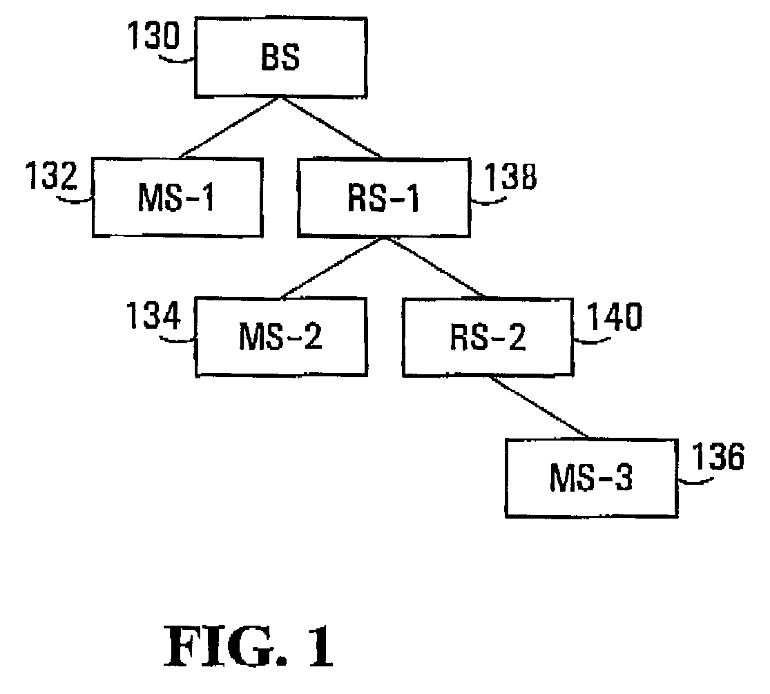
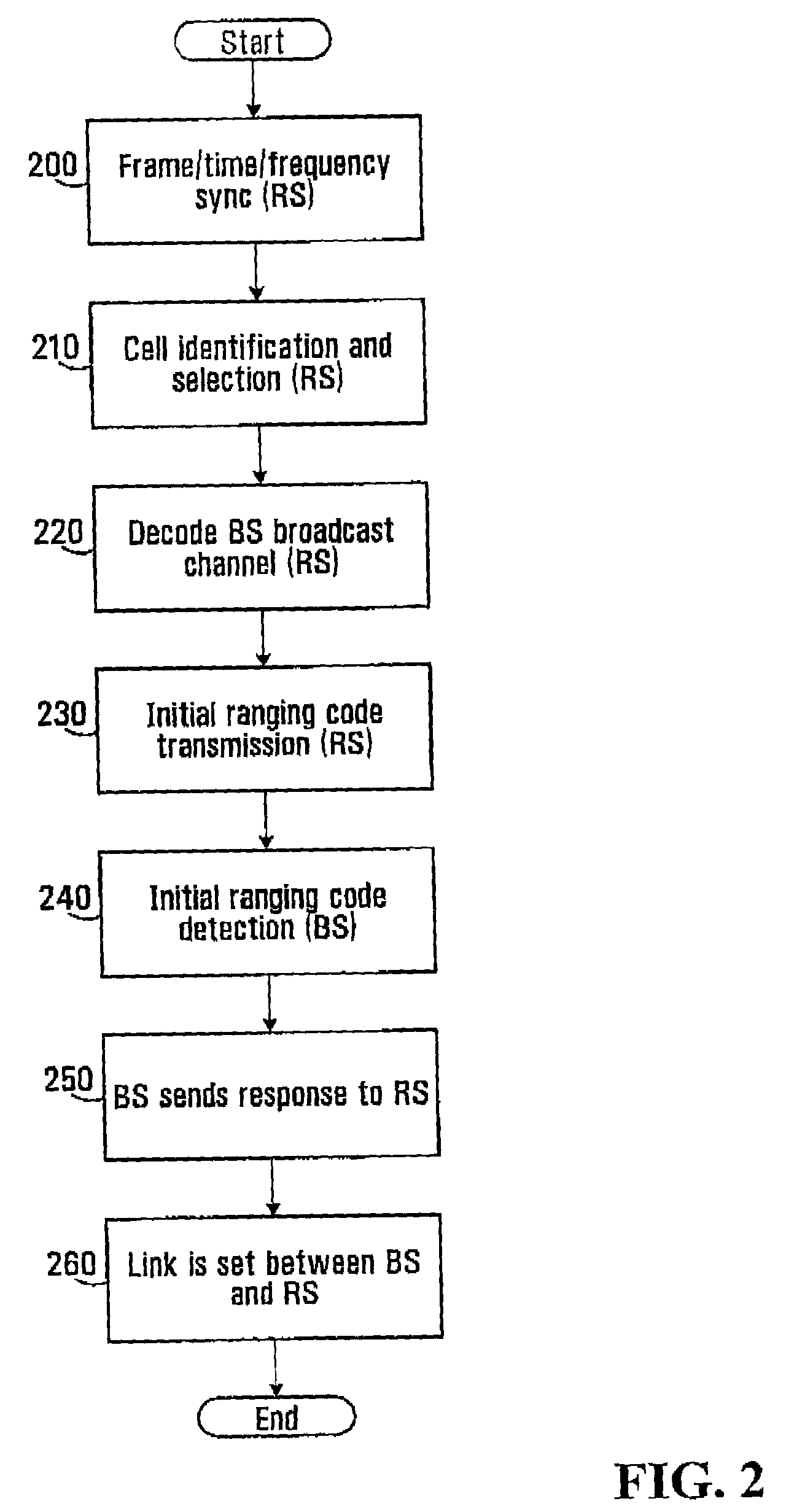
Methods and systems are provided for use with wireless networks having once or more cell in which each cell includes a base station (BS), at least one relay station (RS) and at least one mobile station (MS). The at least one relay station can be used as an intermediate station for providing communication between the BS and MS. Methods are provided for an RS to initially access the network, access of the RS by MSs initially accessing the network, methods of allocating OFDM resources for communicating between the BS, RS and / or MS for example dividing transmission resources into uplink and downlink transmissions, and methods of inserting pilot symbols into transmission resources used by the RS. In some embodiments on the invention, the methods are consistent and / or can be used in conjunction with existing standards such as 802.16e.

Description

RELATED APPLICATIONS[0001]This application claims the benefit of U.S. Provisional Patent Application Nos. 60 / 735,940 filed on Nov. 10, 2005, 60 / 809,341 filed on May 31, 2006, 60 / 822,816 filed on Aug. 1, 2006 and 60 / 822,960 filed on Aug. 21, 2006, which are all hereby incorporated by reference in their entirety.FIELD OF THE INVENTION[0002]The invention relates to the field of wireless communications, more specifically to systems and methods for supporting Orthogonal Frequency Division Multiplexed (OFDM) communication using relays.BACKGROUND OF THE INVENTION [0003]Orthogonal frequency division multiplexing (OFDM) is a form of multiplexing that distributes data over a number of carriers that have a very precise spacing in the frequency domain. The precise spacing of the carriers provides several benefits such as high spectral efficiency, resiliency to radio frequency interference and lower multi-path distortion. Due to its beneficial properties and superior performance in multi-path fa...

Claims


Application Information

Patent Timeline
IPC IPC(8): H04B7/14H04W4/00H04W16/00H04W16/02H04W16/26H04W52/34H04W72/06
CPCH04B7/2606H04L27/2613H04L5/0023H04L5/0035H04L5/0037H04L5/0044H04L5/0048H04L25/0204H04L25/0226H04L25/0232H04L25/03866H04L27/2655H04W16/26H04W52/34H04W72/06H04W84/047H04B7/2615H04W72/563
Inventor MA, JIANGLEIZHANG, HANGZHU, PEIYINGFONG, MO-HANTONG, WENJIA, MING
Owner APPLE INC
Why Eureka
Eureka Blog
Learn More