Power supply system

Active Publication Date: 2009-12-10
SHARP KK
View PDF3 Cites 182 Cited by
  • Summary
  • Abstract
  • Description
  • Claims
  • Application Information

AI Technical Summary

Benefits of technology

[0029]In view of the above problems, the present invention provides a power supply system capable of smoothing the photovoltaic generation output, and enabling time shift.
[0043]According to the present invention, the total power of each storage battery can be obtained. One particular storage battery is prevented from being overly used. Furthermore, the present invention does not require a complex control, and thus a power supply system of the present invention can be realized with an extremely simple circuit.

Problems solved by technology

As there is loss in conversion even with a high efficiency conversion circuit, it is not suited for use of frequently repeating charge and discharge.
Therefore, it is not suited for smoothing energy with large power variation such as natural energy.
Thus, if the solar battery is operation the storage battery voltage when the generated insolation amount to the solar battery is sufficient, the solar battery operates at an extremely bad efficiency.
Most systems annexed with the conventional storage battery have the storage battery annexed for emergency, the frequency of such storage battery being charged from the solar battery is small and thus the efficiency is not given much importance.
However, frequent charging and discharging of the storage battery system are necessary to constantly smooth the output of photovoltaic generation having large power variation.
The electric circuit including the conversion device generally requires a base current, where the efficiency is satisfactory if the electric circuit operates near rating capacity, and microscopic power conversion leads to unsatisfactory efficiency.
Therefore, when charging the output of photovoltaic generation in the storage battery, the output of the photovoltaic generation is small if the insolation is weak as in dawn or before sunset, and thus the power is consumed only to operate the conversion device, and the efficiency degrades.

Method used


Image

  • Power supply system
  • Power supply system
  • Power supply system

Examples


first embodiment

[0098]The power supply system of the first embodiment includes a DC power supply string in which a storage battery is connected in parallel to a DC power supply; a DC / AC power conversion device for connecting the DC power supply string to a power system or a load; and a switch between the DC power supply and the storage battery. An output power of the DC power supply or a combined output power of the DC power supply and the storage battery is switched and supplied to the DC / AC power conversion device by the switch. The output power of the DC power supply is thereby smoothed, and time shift becomes possible.

[0099]The DC power supply is typically a solar battery, but may be a wind power generator or a fuel battery. It may also be a device combining the solar battery and the wind power generator, the solar battery and the fuel battery, or the wind power generator and the fuel battery.

[0100]The first embodiment will be described with the DC power supply as the solar battery. Therefore, ...

example 1-1

System Configuration

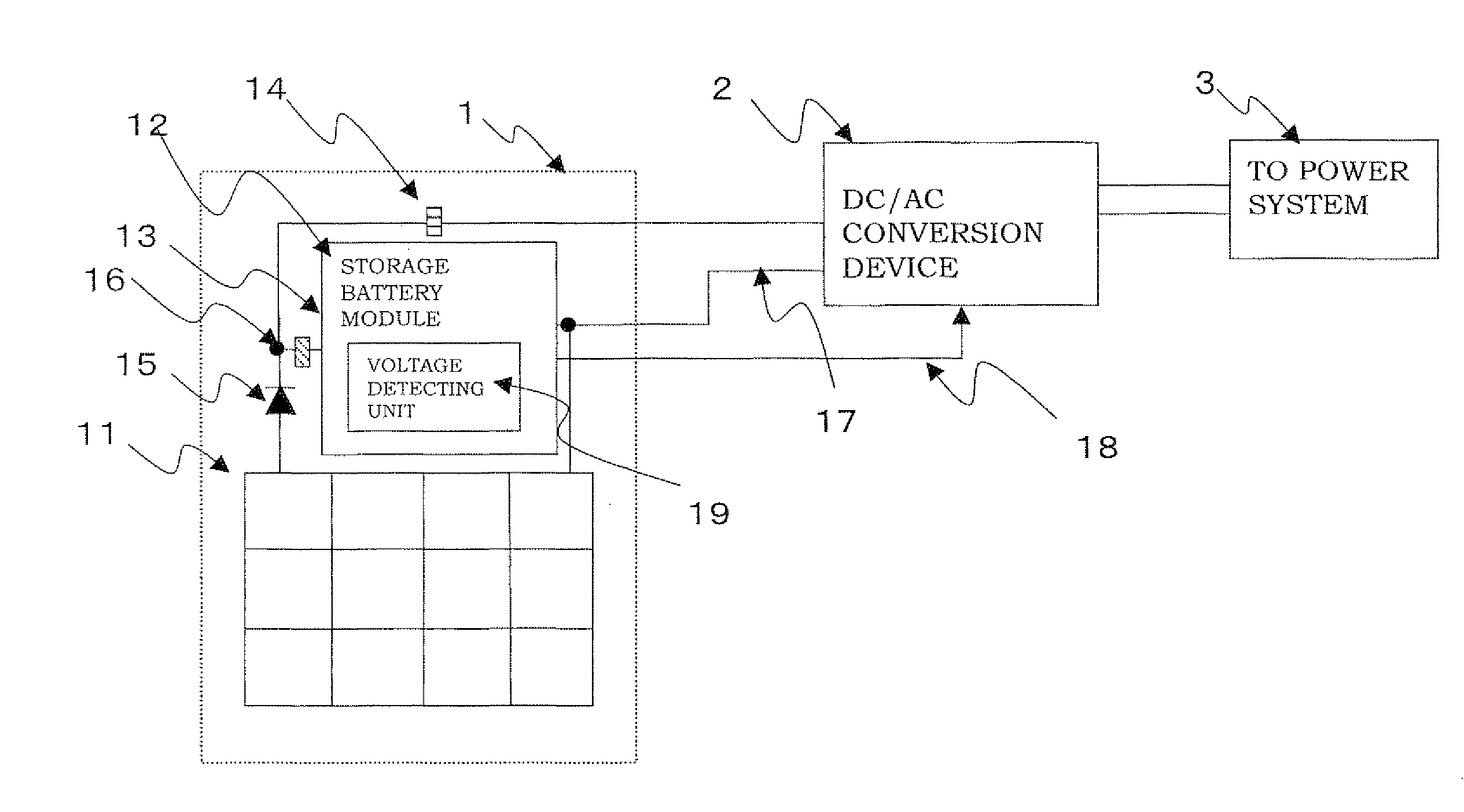
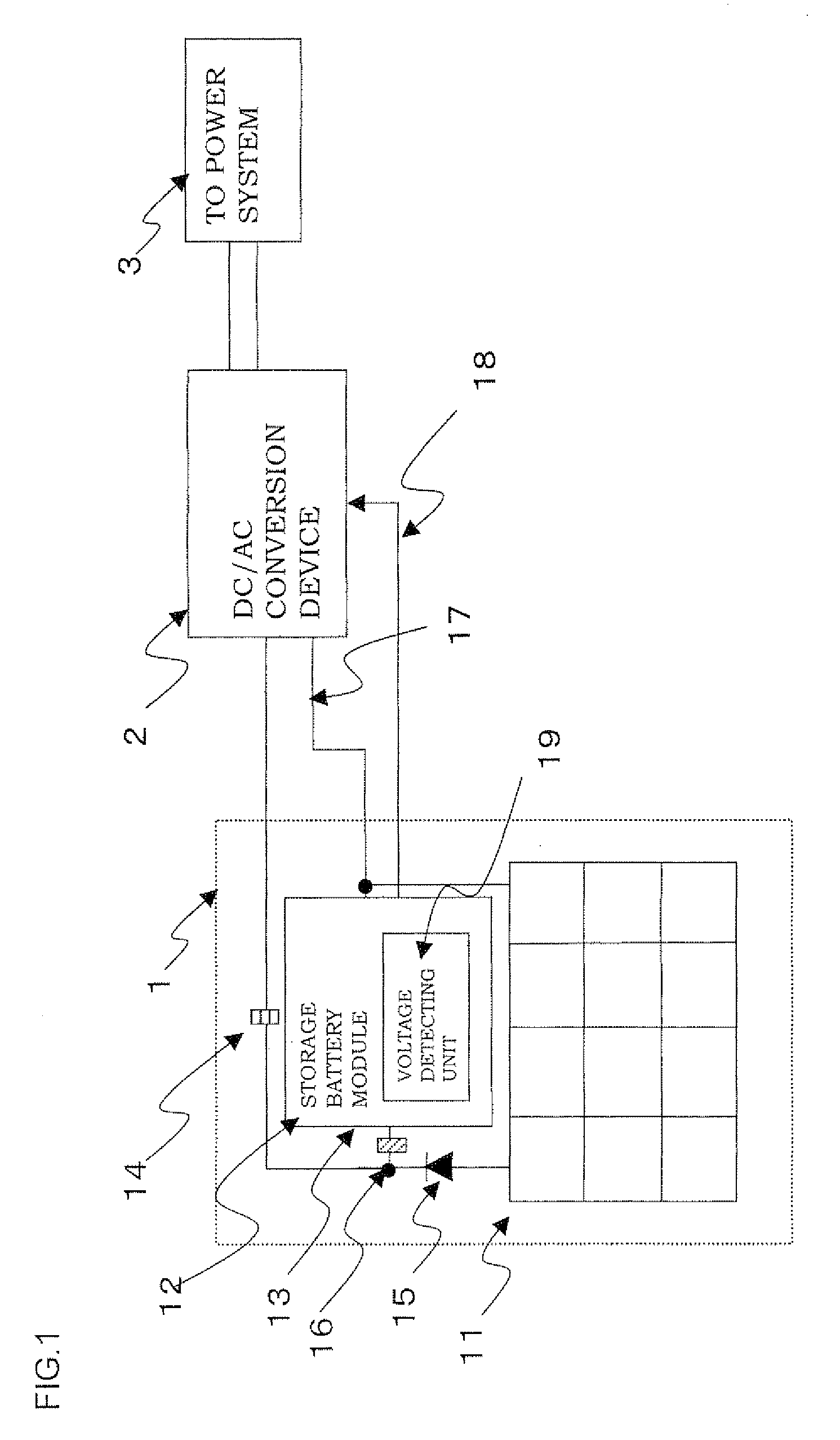
[0164]FIG. 1 is a view showing one example of a configuration of a power supply system of example 1-1. The solar battery module 11 is configured by twelve thin-film crystal solar battery panels having a maximum power point voltage of Vpm=51 V and Isc=2 A, 85 W lined in four by three. The storage battery module 12 has a configuration in which the lithium ion battery of 5.7 Ah is in series of forty-eight, and is configured with a circuit section including a protective circuit and a power counter. The solar battery string 1 of such configuration is connected in parallel by way of the backflow prevention element 15 arranged so that the power of the storage battery module 12 does not backflow to the solar battery module 11. The protective circuit is configured by a commercially available voltage monitoring IC, FET, control CPU, and the like, and has a function of opening the circuit when detecting voltage abnormality etc., and protecting the battery. The power counter...

example 1-2

[0183]In example 1-2, operation was performed according to the system similar to example 1-1 with only the control method changed.

[0184]The operating condition is as follows.

[0185](1) Charge until full charge.

[0186](2) Output with the storage battery device separated when full charge is reached, and the control method changed to the maximum power point tracking.

[0187](3) Perform 300 W output in 12:00 to 14:00 (one hour).

[0188]The operation result is shown in FIG. 8. As apparent from the result, the generated power in the morning can be shifted to 12:00 to 14:00. The easy outputting of only the generated power of the solar battery to the power system by maximum power point tracking according to the situation, and adding the output of the solar battery and the output of the storage battery module and smoothing the same for output can be easily switched.

[0189]Moreover, the power amount actually obtained in the example (only the charging / discharging period) is 96.3% (excluding charging / ...


PUM


Abstract

A power supply system capable of smoothing photovoltaic generation output, and enabling time shift is provided. A power supply system including a DC power supply string in which a storage battery is connected in parallel to a DC power supply; and a DC / AC power conversion device for connecting the DC power supply string to a power system or a load is provided. A switch is connected between the DC power supply and the storage battery, where an output power of the DC power supply or a combined output power of the DC power supply and the storage battery is switched and supplied to the DC / AC power conversion device by the switch. The photovoltaic generation output is thereby smoothed, and time shift is enabled.

Description

BACKGROUND OF THE INVENTION[0001]1. Field of the Invention[0002]The present invention relates to power supply systems including a DC power supply string in which a direct current (DC) power supply for outputting a DC power from a power generator such as solar battery, wind power generator, and fuel battery and a storage battery are connected in parallel; in particular, to a power supply system for smoothing the power variation of the DC power supply and time shifting the output power of the DC power supply.[0003]The present invention also relates to a power supply system for converting the output power of the DC power supply which generated power amount greatly varies according to environment without requiring a complex control. The present invention also relates to a power supply system capable of supplying maximum power by equalizing each battery voltage so that one of a plurality of storage batteries is not overly used, and obtaining a total power of each storage battery.[0004]2....

Claims


Application Information

Patent Timeline
IPC IPC(8): H02J3/32H02J7/35G06F19/00
CPCH02J7/35Y02E10/563Y02E10/566Y02E10/763H02J3/385H02J3/386Y02E10/58H02J3/383H02J2300/28H02J2300/26H02J2300/24H02J3/381Y02E10/56Y02E10/76
Inventor YAMADA, KAZUOMATSUI, RYOJIYAGI, AYUMIYOSHIMI, NAOKI
Owner SHARP KK
Why Eureka
Try Eureka