Elastomeric dispensing pump that can be made with as few as two components

Inactive Publication Date: 2009-12-10
MABEL
View PDF24 Cites 32 Cited by
  • Summary
  • Abstract
  • Description
  • Claims
  • Application Information

AI Technical Summary

Benefits of technology

[0023]The present invention overcomes the above-mentioned and / or other problems, and relates to a fluid dispensing pump that can be manufactured from as few as two easily assembled parts that is reliable and user-friendly, and among various advantages, offers improved ergonomics and greater flexibility of design and esthetics than existing art.
[0032]An alternate embodiment, the integral pump top (300) has a rigid or semi-rigid actuator portion (314) bound to, or imbedded into, the resilient self-restoring pump wall (323), and preferably connected to the base attachment portion of the rigid core (311). The actuator portion (314) may also be connected to the base attachment portion of the rigid core (311) in a spring-like manner for increased pump efficiency. Also, the integral pump top (300) is optionally movable relative to the pump base or rotatable around a central axis between an open position and a closed position so that in an open position the pump operates to dispense fluid, and in a closed position the pump is shut-off and inoperable.
[0034]A further object of the present invention is to provide a dispensing pump employing an optional self-closing and positive shut-off mechanism which is inexpensive to manufacture and assemble, which is user-friendly, and which provides increased leak-proofing without spillage in closed position. Self-closing is desirable to avoid deterioration of the substance remaining in the dispensing passageway and to ensure that the dispensing slit or orifice remains clean. Also fluid leakage is always a concern throughout the life of the pump. When shipping the pump, internal container pressure may fluctuate as a result of temperature changes and / or handling shocks and may create leakage, even when the pump is not actuated; therefore, an efficient positive shut-off mechanism is a highly desirable feature.

Problems solved by technology

Such pumps are rather complex, having nine parts or more and involve the use of one-way ball valves, various springs, sliding pistons, sealing elements and related engineering elements that require complex tooling and assembly.
They also have a size limitation as it becomes difficult to maintain proper dimensional tolerance when size increases; likewise, miniaturization is limited due to the large number of components.
They also have design restrictions that limit their esthetics and reduce design creativity by being limited to cylindrical shapes for their main body and being rather bulky.
However, such pumps present assembly challenges for mass-production as the flexible parts tend to deform during assembly which raises positioning issues and may result in unacceptable levels of defective parts, especially when assembly involves groves, annular rings or sliding seals, and tight fitting is required for proper sealing.
They also present reliability issues as it can be difficult to get a sealing connection between the flexible components and the rigid components.
Furthermore, most pumps with flexible walls tend to dispense fluid when sufficient positive pressure is applied to the inlet port of the pump which may occur upon sufficient temperature change causing a substantial increase of the air pressure inside a container, especially when the fluid inside the container is volatile.
Such spontaneous fluid dispensing without user intervention is highly undesirable.
Considering the prior art, a few patents disclose dispensing pumps that can be made with as few as two components: a rigid pump base and an elastomeric component forming a pump body, and most have spontaneous dispensing issues and present mass-production challenges as the requirement for tight fitting and rather complex geometry of a flexible part and a rigid part greatly complicates automated assembly.
Such setting requires a dual compartment and raises reliability and assembly issues.U.S. Pat. No. 3,752,366 discloses a two-piece suction pump with a deformable member, having an annular groove and an annular ring in sealing engagement to a cap member.U.S. Pat. No. 3,820,689 discloses an elastomeric pump with a rigid base member and an elastomeric upper member having a dome-shaped part and an extending elongated lip or flat member.
There are some problems with this type of design: for example, pressure applied to the pump will tend to peel off the “integral resilient upper member” from the “base member”, whether it is mechanically bound (with a grove for instance) or glued (the method favored by the patent).
Also, automated assembly of such a pump in a production line may be very difficult to accomplish in practice.U.S. Pat. No. 6,755,327 teaches a complex pump using a sliding seal.
This can be problematic.
Also, a “stationary end sealed to the pump base about the inlet passageway” may raise leakage issues.U.S. Pat. No. 6,910,603 also teaches a fairly complicated pump.
The “annular barrier seal (23) in rubbing contact between the upper (10) and lower (11) components” may not be reliable and may be prone to leakage because of the length of the seal is the entire perimeter.

Method used


Image

  • Elastomeric dispensing pump that can be made with as few as two components
  • Elastomeric dispensing pump that can be made with as few as two components
  • Elastomeric dispensing pump that can be made with as few as two components

Examples


Embodiment Construction

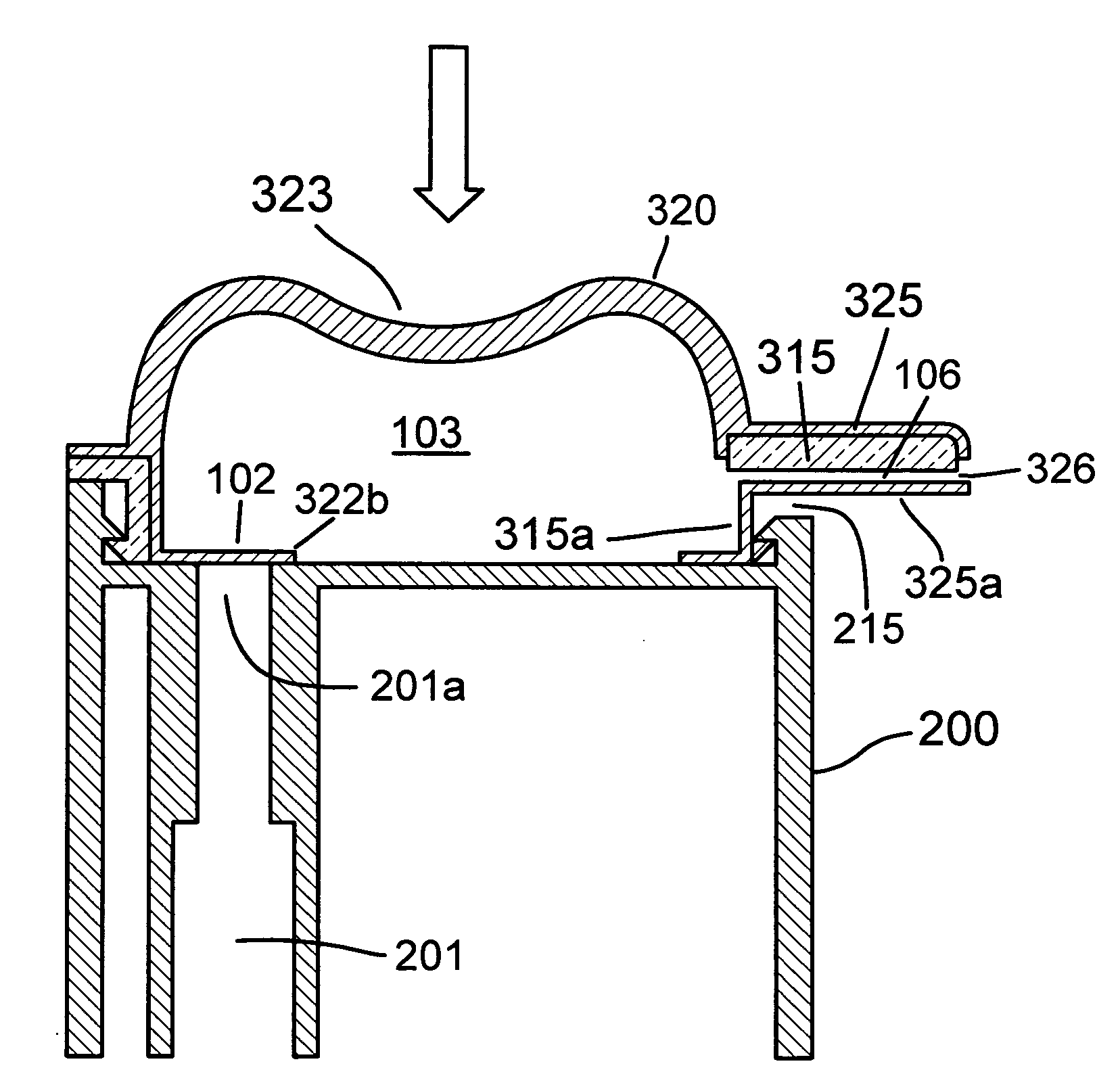
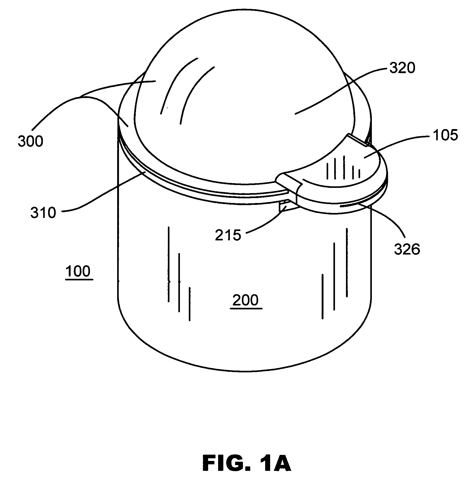
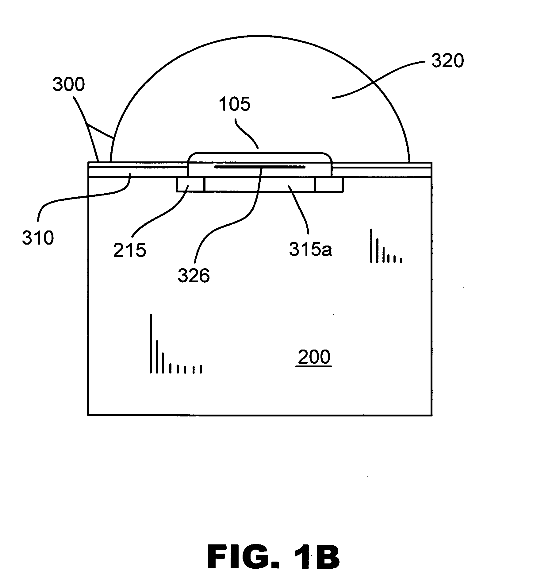
[0066]The present invention relates to a fluid dispensing pump that can be fabricated with as little as two easily assembled separate parts: a pump base part and an integral pump top part that is securely attached to the pump base in a fluid-tight manner, the pump top part having a rigid core and a self-restoring resilient layer. The two parts of the pump top can be made by multi-material molding in the same mold or over-molding whereas the core is made first and then placed in a mold again to over-mold the elastomeric layer.

[0067]The rigid core and the elastomeric layer may be joined through: 1) a mechanical binding such as groves, asperities, holes or other surface means 2) a chemical bind such as interface solidification of melted portions of the two materials. 3) or they may just overlay in a weak binding. Some embodiments of the present invention do not require a particularly strong binding because the elastomeric layer is self-sealing; however, embodiments that have rotating c...


PUM


Abstract

A fluid dispensing pump that can be manufactured from as few as two parts: a stationary pump base (200) provided with an inlet passageway (201), and an integral pump top (300) provided with a fluid-tight attachment to the pump base and including a generally rigid core (310) and a self-restoring elastomeric layer (320). The generally rigid core (310) has a base attachment portion (311) and a dispensing valve core (315). The elastomeric layer (320) includes a resilient self-restoring pump wall (323) and a dispensing valve membrane (325). Upon assembly of the pump base and the pump top, a fully functional dispensing pump (100) is created with an inlet passageway (101), a one-way inlet valve (102), a self-restoring resilient pump cavity of variable volume (103) and a one-way dispensing valve (105). The one-way dispensing valve is preferably self-closing. The integral pump top (300) may have a rigid or semi-rigid actuator portion (314) bound to or imbedded into the resilient self-restoring pump wall (323). The dispensing pump of the present invention may have a valved venting passage for those applications that require it and may have a secure lock-in mechanism for leakage prevention during storage or transportation.

Description

BACKGROUND[0001]1. Field of the Invention[0002]The present invention relates generally to the field of fluid dispensing pumps and more particularly to an elastomeric dispensing pump with optional self-closing, positive shut-off and valved venting passage mechanisms and that can be made with as few as two easily assembled components.[0003]2. Description of the Prior Art[0004]Dispensing pumps are well known in the art and are commonly used for dispensing liquids having widely varying flow characteristics and viscosities. The form of discharge from these pumps varies from a fine spray to a slow moving flow. Common examples are numerous dispensers found on the market such as container-mounted, finger-operated dispensing pumps for such products as hand creams, lotions, shampoos, liquid soap or window cleaner as well as wall-mounted dispensers such as soap dispensers found in public bathrooms.[0005]Reciprocating piston pumps are the most widely used type of dispensing pumps. Such pumps ar...

Claims


Application Information

Patent Timeline
IPC IPC(8): B65D37/00
CPCB05B11/0018B05B11/0027B05B11/3052B05B11/3033B05B11/3032B05B11/00442B05B11/1033B05B11/1032B05B11/1052B05B11/0039
Inventor LAVABRE, MARCEL
Owner MABEL
Why Eureka
Try Eureka