
Vehicle equipped with electrical storage device, and charging cable

a technology of electrical storage device and charging cable, which is applied in the direction of hybrid vehicles, electric devices, propulsion by batteries/cells, etc., can solve the problems of disconnection, difficulty in properly detecting leakage, etc., and achieve the effect of quick repair

Inactive Publication Date: 2009-12-10
TOYOTA JIDOSHA KK
View PDF3 Cites 49 Cited by
  • Summary
  • Abstract
  • Description
  • Claims
  • Application Information

AI Technical Summary

Benefits of technology

[0018]According to the aspects of the invention, it is possible to immediately locate a fault when charging is performed, and, therefore, it is possible to quickly undergo repair, or the like.

Problems solved by technology

However, the power cable is repeatedly attached to and detached from the vehicle body, so it is necessary to consider that a wire disconnection may occur in the cable.
Particularly, if there is a disconnection in the ground line, it is difficult to, for example, properly detect a leakage.

Method used


Image

  • Vehicle equipped with electrical storage device, and charging cable
  • Vehicle equipped with electrical storage device, and charging cable
  • Vehicle equipped with electrical storage device, and charging cable

Examples


first embodiment

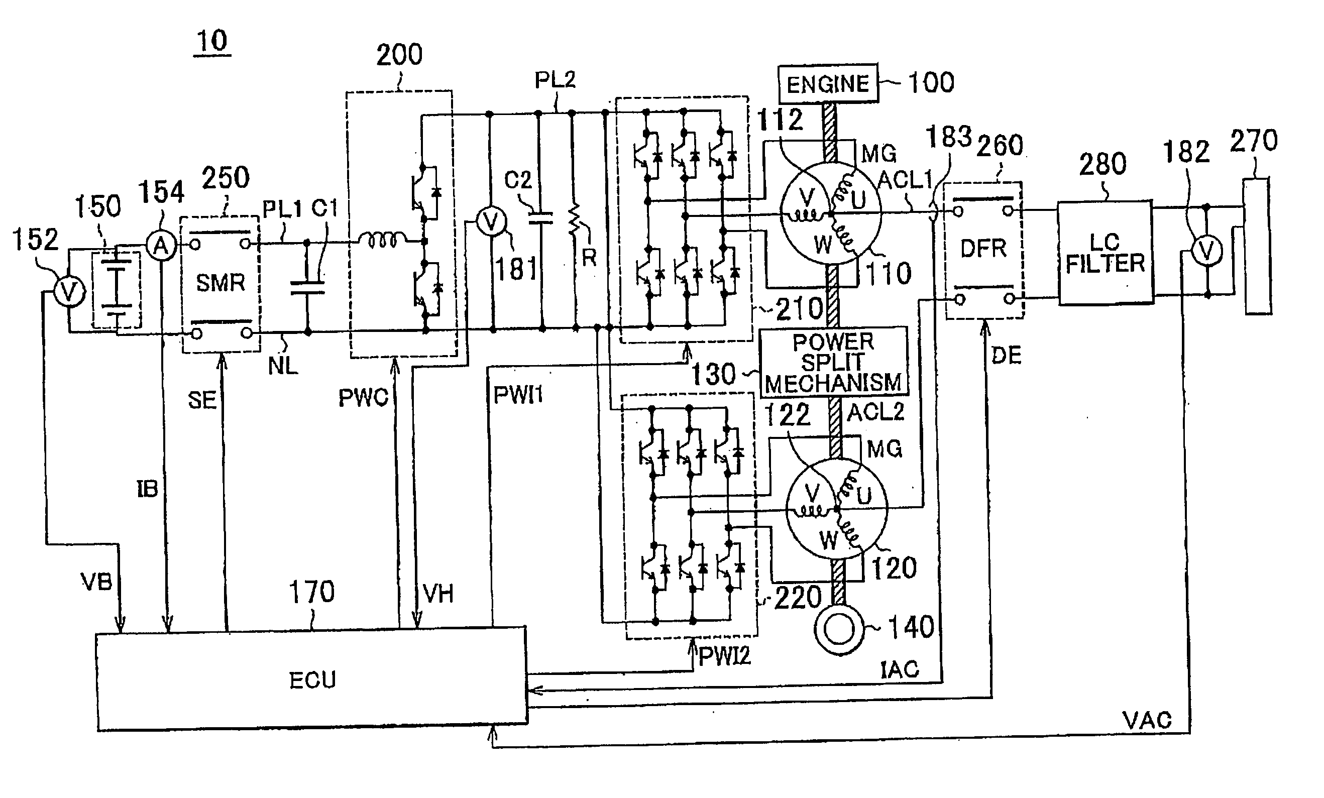
[0031]FIG. 1 is a view that shows a powertrain configuration of a hybrid vehicle, which is an example of an electric vehicle, according to an embodiment of the invention.

[0032]Referring to FIG. 1, the hybrid vehicle 10 includes an engine 100, a first motor generator (MG) 110, a second motor generator (MG) 120, a power split mechanism 130, and drive wheels 140.

[0033]The hybrid vehicle 10 further includes an electrical storage device 150, a system main relay (SMR) 250, a step-up converter 200, a first inverter 210, a second inverter 220, a first capacitor C1, a second capacitor C2, a discharging resistance R, and a voltage sensor 181.

[0034]The hybrid vehicle 10 further includes power input lines ACL1 and ACL2, a dead front relay (DFR) 260, an LC filter 280, a charging inlet 270, a voltage sensor 182, a current sensor 183, and an ECU 170.

[0035]The engine 100, the first MG 110 and the second MG 120 are coupled to the power split mechanism 130. Then, the hybrid vehicle 10 runs on the dri...

second embodiment

[0100]FIG. 10 is a schematic configuration diagram of a portion related to charging of a hybrid vehicle according to a second embodiment.

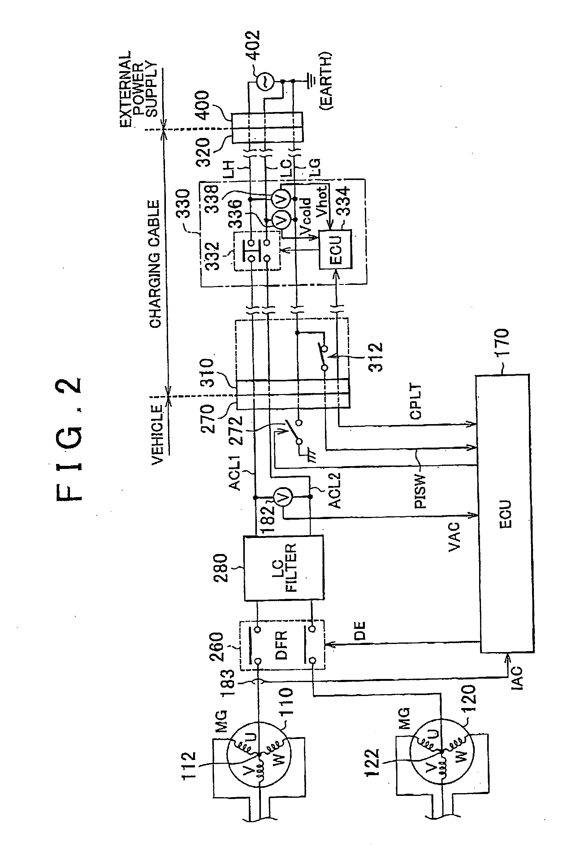
[0101]The configuration shown in FIG. 10 includes a GND relay 273 instead of the GND relay 272 in the configuration shown in FIG. 2. The GND relay 273 is provided inside the CCID 330 together with the charging relay 332. Note that the other portions of the configuration shown in FIG. 10 are already described with reference to FIG. 2, so the description thereof is not repeated. In addition, the ground line LG is checked for a disconnection by carrying out control similar to the control described with reference to FIG. 7 and FIG. 9, so the description thereof is not repeated.

[0102]As described in the second embodiment, by incorporating the GND relay not in the vehicle but in the CCID 330, it is possible to accurately detect a disconnection in the ground line for models that are not equipped with the GND relay.

Alternative Embodiment

[0103]In the config...


PUM


Abstract

A vehicle includes a charging inlet for connection with a ground line and a pair of power lines used to charge an electrical storage device from outside the vehicle; a terminal of the charging inlet for connection with the ground line; and a GND relay that connects the terminal to a body earth of the vehicle. Desirably, the vehicle further includes an ECU that controls charging of the electrical storage device. Before charging of the electrical storage device is started after the pair of power lines and the ground line are connected to the charging inlet, the ECU opens the GND relay and then determines whether there is a disconnection in the ground line.

Description

INCORPORATION BY REFERENCE[0001]The disclosure of Japanese Patent Application No. 2008-147964 filed on Jun. 5, 2008 including the specification, drawings and abstract is incorporated herein by reference in its entirety.BACKGROUND OF THE INVENTION[0002]1. Field of the Invention[0003]The invention relates to a vehicle equipped with an electrical storage device, and a charging cable for charging the electrical storage device from outside the vehicle.[0004]2. Description of the Related Art[0005]Japanese Patent Application Publication No. 5-276674 (JP-A-5-276674) describes a charging apparatus for an electric vehicle. The charging apparatus includes a charging cable that has a pair of power lines for charge output and a ground line for connection with a vehicle body. Before charging is started, electric potentials of these power lines and ground line are detected to check a potential difference between a storage battery and the vehicle body. When it is determined that there is a leakage,...

Claims


Application Information

Patent Timeline
Patent Type & Authority Applications(United States)
IPC IPC(8): B60W10/26H02J7/04
CPCB60L3/0046Y02T90/14B60L11/14B60L11/1812B60L11/1814B60L11/1818B60L11/1824B60L15/007B60L2220/14B60L2220/54B60L2230/12B60W10/26Y02T10/6217Y02T10/6269Y02T10/641Y02T10/7005Y02T10/7077Y02T10/7088Y02T90/121Y02T90/127B60L11/123Y10S903/907B60L53/16B60L53/22B60L50/61B60L50/16B60L53/24B60L53/30B60L53/18B60L53/68Y02T10/62Y02T10/64Y02T10/7072Y02T10/70Y02T90/12Y02T90/16Y04S30/12Y02T90/167
Inventor FUJITAKE, YOSHINORI
Owner TOYOTA JIDOSHA KK
Learn More