
Toner composition for preventing image blocking

Inactive Publication Date: 2009-12-03
EASTMAN KODAK CO
View PDF8 Cites 20 Cited by
  • Summary
  • Abstract
  • Description
  • Claims
  • Application Information

AI Technical Summary

Benefits of technology

[0009]A feature of the present invention is to provide an electrophotographic toner, which is capable of resisting print sticking at relatively high temperature and humidity conditions, such as 55° C. and 95% relative humidity for a 24 hours exposure.
[0011]Another feature of the present invention is to provide an electrophotographic toner, which provides improved print sticking resistance and yet does not affect the release fluid used in a contact roller fusing method.
[0014]This invention is directed to toner and developer useful for clectrographic printing, and more particularly to a protective toner composition that helps prevent images and prints, produced via electrophotography, from sticking and blocking when subjected to elevated temperature and relative humidity conditions. Such electrographic printing preferably includes the steps of forming a desired print image, electrographically, on a receiver member utilizing cyan, yellow, magenta, and black (CYMK) color marking particles; and in the area of the formed print image, where protection from sticking or blocking is desired, selectively forming a protective toner layer, utilizing a protective toner of this invention whose composition is different from that of the CYMK marking particles of the desired print image. In particular, the protective toner comprises a binder having a higher Tg than that of the color marking material toner binder, and further comprises ethylene-bis-stearamide as an additive. In the preferred embodiment, the protective toner of this invention is clear, i.e., it does not contain pigment and is used over the color image formed with the standard CYMK toners.
[0015]In one embodiment, a desired optimum performance is achieved when toner particle of this invention are placed uniformly across the entire color 5 image to provide the protective layer. In such case, a uniform protective layer would be present over the entire image regardless of the image content. The amount of inventive toner required to form the protective layer would be much higher in this case, but the final image has a uniform gloss and feel. In another embodiment, inventive toner is used only where the higher amount of standard color toner is present in the image. This lowers the amount of the inventive toner required for the protection, by placing the toner of this invention only in the darker areas where the typical sticking problem is often observed. In general, the lighter areas of an image do not exhibit print sticking problem as compared with the higher density areas.
[0020]The present invention also relates to a method of improving toner image sticking resistance using the above-identified toner formulation of the present invention.

Problems solved by technology

Initially, the color print was primarily limited to marketing collaterals.
However, a combination of sudden transformation of photography to digital format and improvements made in the quality of digital printing has placed additional constraints on electrophotographic prints that were not applicable for outputs from copiers.
If the Tg of the toner binder is too high, then adequate polymer flow, necessary for proper fixing not achieved.
For this reason, useful range of the glass transition temperature for toner binder is typically limited to below 60° C., and typically from about 50 to less than 60° C. Also, when molecular weight of the toner polymer is too low, the toner tends to get very brittle which adversely affects the developer life and print physicals.
When electrograpbic images made with the toner binder as described above is subjected to high temperature, then print sticking becomes a common occurrence.
As a consequence, a set of prints or a photo album can exhibit signs of sticking or “bricking” or “blocking” when they are subjected to such extreme temperature and relative humidity conditions.
Such damage is irreversible and renders the prints useless.

Method used


Image

  • Toner composition for preventing image blocking
  • Toner composition for preventing image blocking
  • Toner composition for preventing image blocking

Examples


Embodiment Construction

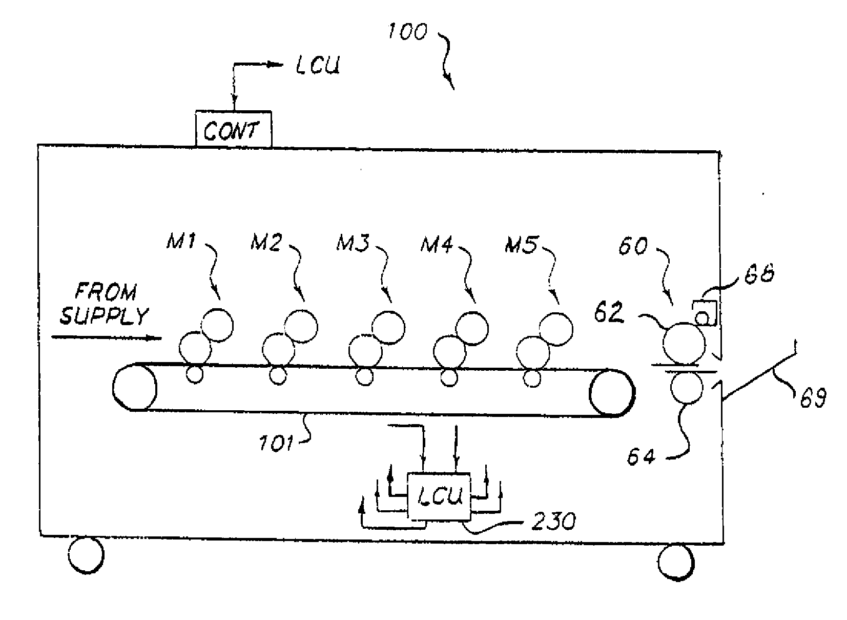
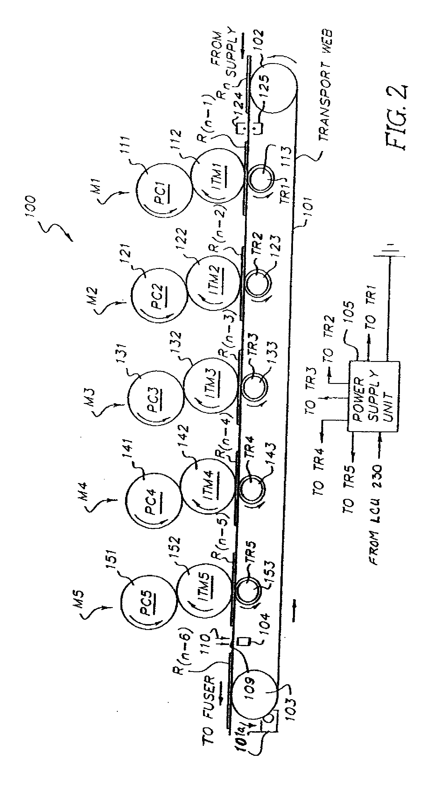
[0026]In electrophotography, once the latent image has been developed and the developed image is then transferred to the substrate, it needs to be fixed in order for it to be well adhered to the substrate. This can be done by a number of means such as radiant heating or by passing the image through a pair of heated rollers. Of these, a pair of heated rollers is the most commonly used method for fixing an image. Generally, one of the rollers is heated to a higher temperature and may have an optional release fluid applied to its surface. The typical viscosity of the release fluid ranges from 200 cSt to 100,000 cSt at room temperature. For high-speed color applications, release fluid viscosity applied to this roller is typically less than 1000 eSt. This roller is usually referred to as the fuser roller. The other roller is typically heated to a much lower temperature and usually serves the function of applying pressure to the nip as the unfused image is passed through the nip of the tw...


PUM

PropertyMeasurementUnit
Temperatureaaaaaaaaaa
Fractionaaaaaaaaaa

Abstract

Images produced by electrophotography are often subjected to harsh conditions, such as high temperature and high relative humidity conditions. Prints when subjected to face-to-face stacking under these conditions tend to stick and are difficult to separate without damage. Ethylene-bis-stearamide is incorporated in a protective toner formulation employing a toner binder having a higher glass transition temperature than that of the conventional CYMK colored image toners employed to provide a protective layer in fused images. Further, ethylene-bis-stearamide does not interfere with typical oil release additives used in fuser rollers. By combining ethylene-bis-stearamide with polyalkane waxes having a weight average molecular weight of equal to or greater than 2000 and a poly dispersity of less than 2.0, addition protection can be realized.

Description

CROSS-REFERENCE TO RELATED APPLICATIONS[0001]This is a 111A application of Provisional Application Ser. No. 61 / 056,948, filed May 29, 2008.FIELD OF THE INVENTION[0002]This invention relates in general to toner and developer useful for electrographic printing, and more particularly to protective toner composition that helps prevent images and prints, produced via electrophotography, from sticking and blocking when subjected to elevated temperature and relative humidity conditions.BACKGROUND OF THE INVENTION[0003]One common method for printing images on a receiver member is referred to as electrography (also referred to as electrostatography). In this method, an electrostatic image may be formed on a dielectric member by uniformly charging the dielectric member and then discharging selected areas of the uniform charge to yield an image-wise electrostatic charge pattern. Such discharge is typically accomplished by exposing the uniformly charged dielectric member to actinic radiation pr...

Claims


Application Information

Patent Timeline
IPC IPC(8): G03G8/00G03G9/00G03G13/20
CPCG03G9/0821G03G9/0823G03G9/08704G03G9/09733G03G9/09716G03G9/09725G03G9/08782
Inventor TYAGI, DINESHSHERWOOD, WALTER B.GRANICA, LOUISE
Owner EASTMAN KODAK CO
Learn More