
Rear-loaded light emitting diode module for automotive rear combination lamps

a technology of light-emitting diodes and rear combination lamps, which is applied in the direction of semiconductor devices for light sources, lighting and heating apparatus, transportation and packaging, etc., can solve the problems of low optical efficiency, difficulty in assembly, and hesitant to completely abandon the familiarity of bulb/lamp sockets and their accompanying traditional-style optics

Inactive Publication Date: 2009-12-03
OSRAM SYLVANIA INC
View PDF14 Cites 51 Cited by
  • Summary
  • Abstract
  • Description
  • Claims
  • Application Information

AI Technical Summary

Benefits of technology

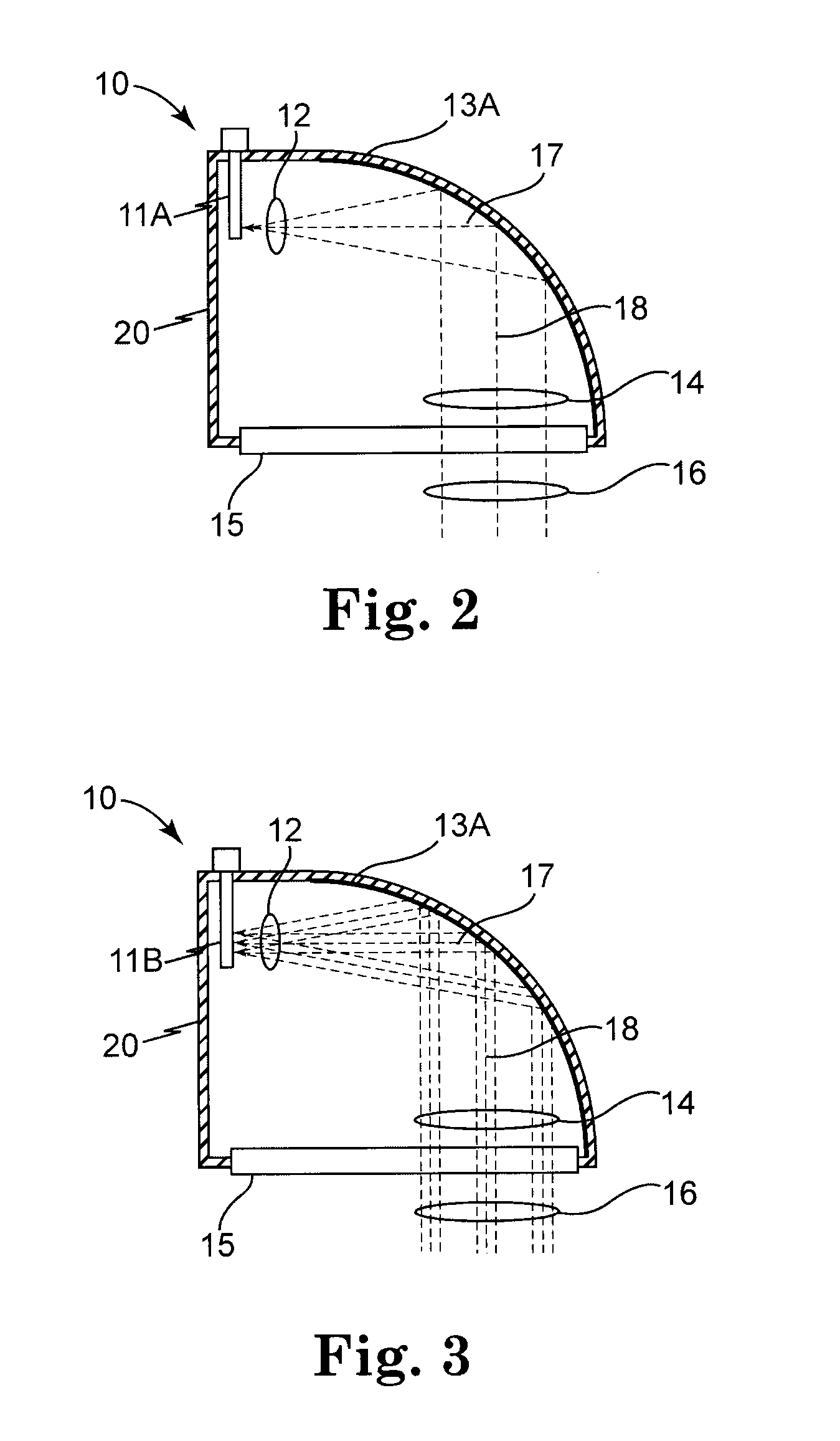
[0030]FIG. 2 is a cross-sectional schematic drawing of a simplified optical path in a rear combination lamp, having a single LED and an un-faceted reflector.
[0031]FIG. 3 is a cross-sectional schematic drawing of a simplified optical p

Problems solved by technology

While they have been eager to adopt LEDs for all of the advantages stated above, they have been hesitant to completely abandon the familiarity of a bulb / lamp with a socket and its accompanying traditional-style optics.
Each of these designs had some drawbacks, such as difficulty during assembly, or a low optical efficiency, caused by losses.
There may be additional polishing steps performed on the part, but such polishing steps add undesirable expense to the light guide, and therefore, to the whole lamp unit.
The longitudinal faces of the light guide are the entrance and exiting faces, and both may introduce loss.
Such reflection loss may be reduced by applying anti-reflection coatings to the longitudinal faces, but this may add undesirable expense to the light guide, and, therefore, to the whole lamp unit.
In addition, there may be additional losses at the longitudinal faces caused by scattering.
Such scattering losses may be reduced somewhat by ensuring that the longitudinal faces are relatively smooth, but in practice, these scattering losses are difficult to eliminate.
There may be scattering losses caused by surface roughness, contaminants, or other imperfections along the transverse face.
As with the scattering losses from the longitudinal faces, the scattering losses from the transverse face may be difficult to eliminate.

Method used


Image

  • Rear-loaded light emitting diode module for automotive rear combination lamps
  • Rear-loaded light emitting diode module for automotive rear combination lamps
  • Rear-loaded light emitting diode module for automotive rear combination lamps

Examples


Embodiment Construction

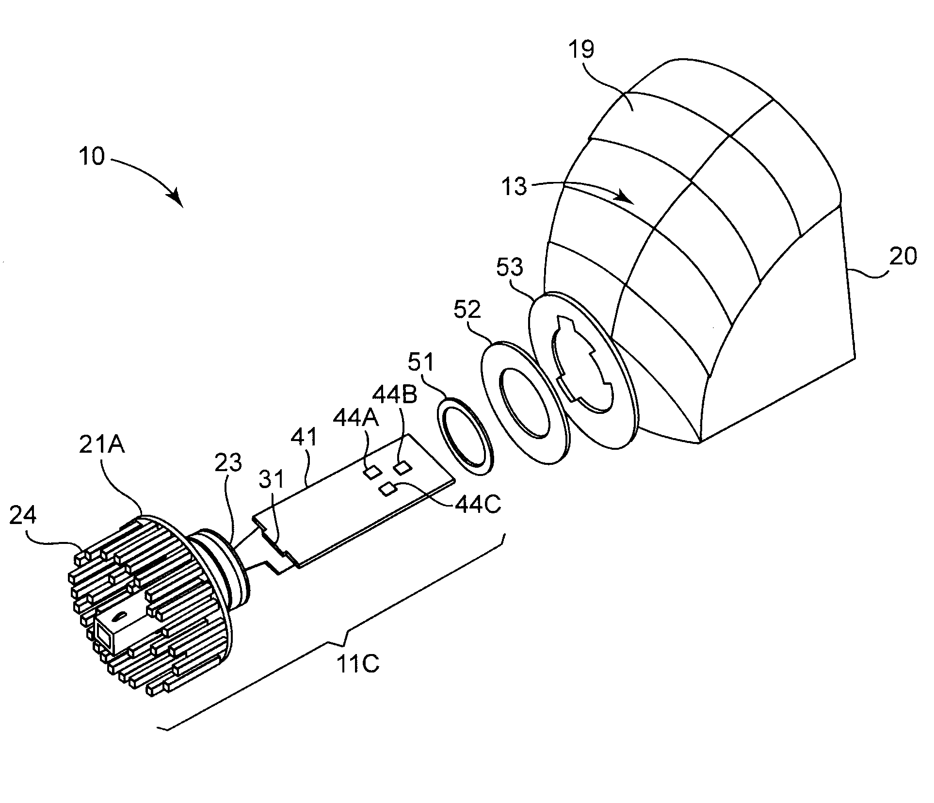
[0041]The light emitting diode (LED) module disclosed herein may be used for exterior vehicle lighting. The LED module may be installed in a light set socket from the back and be replaceable, in a manner similar to that used with conventional incandescent bulbs. The LED module may also be installed and sealed in the reflector housing if a replaceable module is not necessarily needed. The LED module may include optical elements suitable to distribute the light to a reflector that receives light from the LED chip(s) and directs the reflected light toward a viewer. This is disclosed more fully in the detailed description below.

[0042]For typical, known rear combination lamps that use light emitting diodes as their light sources, there have been numerous ways of ensuring that the output light exits the device with the proper orientation. For instance, the first generation system commercially available with the name JOULE used light emitting diodes mounted at a particular angle. The assem...


PUM


Abstract

A rear-loading LED module for a rear combination lamp is disclosed. One or more LEDs are mounted on a printed circuit board that mechanically holds them at the focus of a faceted, parabolic reflector. Light from the LEDs diverges transversely and horizontally, and is collimated by the reflector, and the reflected collimated light is directed in a generally longitudinal direction out of the rear combination lamp, toward the viewer. The LED module itself is generally longitudinally oriented, and is insertable longitudinally into the interior of the reflector from a hole at the vertex of the reflector. The printed circuit board, an optional thermal pad adjacent to the printed circuit board, and a thermally conductive layer adjacent to the optional thermal pad are all generally planar layers, are all generally parallel to each other, and may optionally all have the same footprint. Together, the printed circuit board, the thermal pad and the thermally conductive layer may all form a generally planar ledge.

Description

CROSS-REFERENCE TO RELATED APPLICATIONS[0001]The present application claims priority under 35 U.S.C §119(e) to provisional application No. 61 / 056,738, filed on May 28, 2008 under the title, “Side entry LED light module for automotive rear combination lamp,” and incorporated by reference herein in its entirety. Full Paris Convention priority is hereby expressly reserved.STATEMENT REGARDING FEDERALLY SPONSORED RESEARCH OR DEVELOPMENT[0002]Not ApplicableBACKGROUND OF THE INVENTION[0003]1. Field of the Invention[0004]The present invention is directed to rear combination lamps for automotive lighting systems.[0005]2. Description of the Related Art[0006]For many years, automobiles have employed electric lighting that serves a variety of functions. For instance, lights provide forward illumination (headlamps, auxiliary lamps), conspicuity (parking lights in front, taillights in rear), signaling (turn signals, hazards, brake lights, reversing lights), and convenience (dome lights, dashboard...

Claims


Application Information

Patent Timeline
IPC IPC(8): B60Q1/00H01L33/00H01L33/60
CPCF21K9/00F21V29/81F21S48/1159F21S48/1358F21S48/211F21S48/215F21S48/23F21S48/328F21V7/0008F21V29/004F21Y2101/02F21V29/74F21V29/75F21V29/80F21S48/1104F21Y2115/10F21S41/19F21S41/192F21S41/334F21S43/19F21S43/14F21S43/30F21S45/47B60Q1/26F21V23/00F21V29/00F21V29/763F21V29/89
Inventor LUO, HONGLIU, ZHAOHUAN
Owner OSRAM SYLVANIA INC
Learn More