
Microstructure device including a metallization structure with self-aligned air gaps between closely spaced metal lines

a microstructure device and air gap technology, applied in semiconductor devices, semiconductor/solid-state device details, electrical devices, etc., can solve the problems of limiting device performance, signal propagation delay caused, and inefficient deposited copper, so as to avoid cost-intensive sophisticated lithography processes, reduce overall permittivity, and high degree of flexibility

Inactive Publication Date: 2009-12-03
ADVANCED MICRO DEVICES INC
View PDF27 Cites 203 Cited by
  • Summary
  • Abstract
  • Description
  • Claims
  • Application Information

AI Technical Summary

Benefits of technology

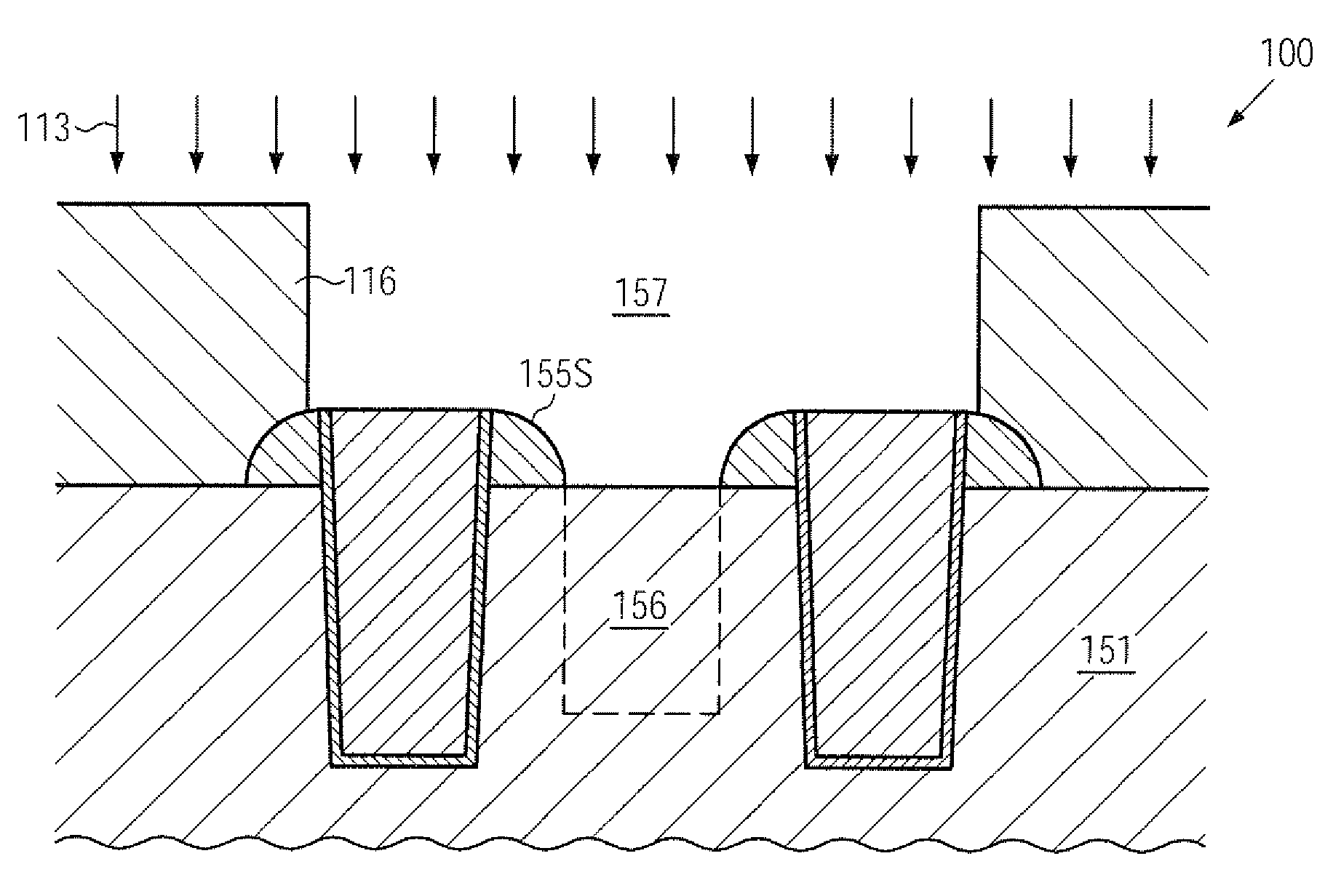
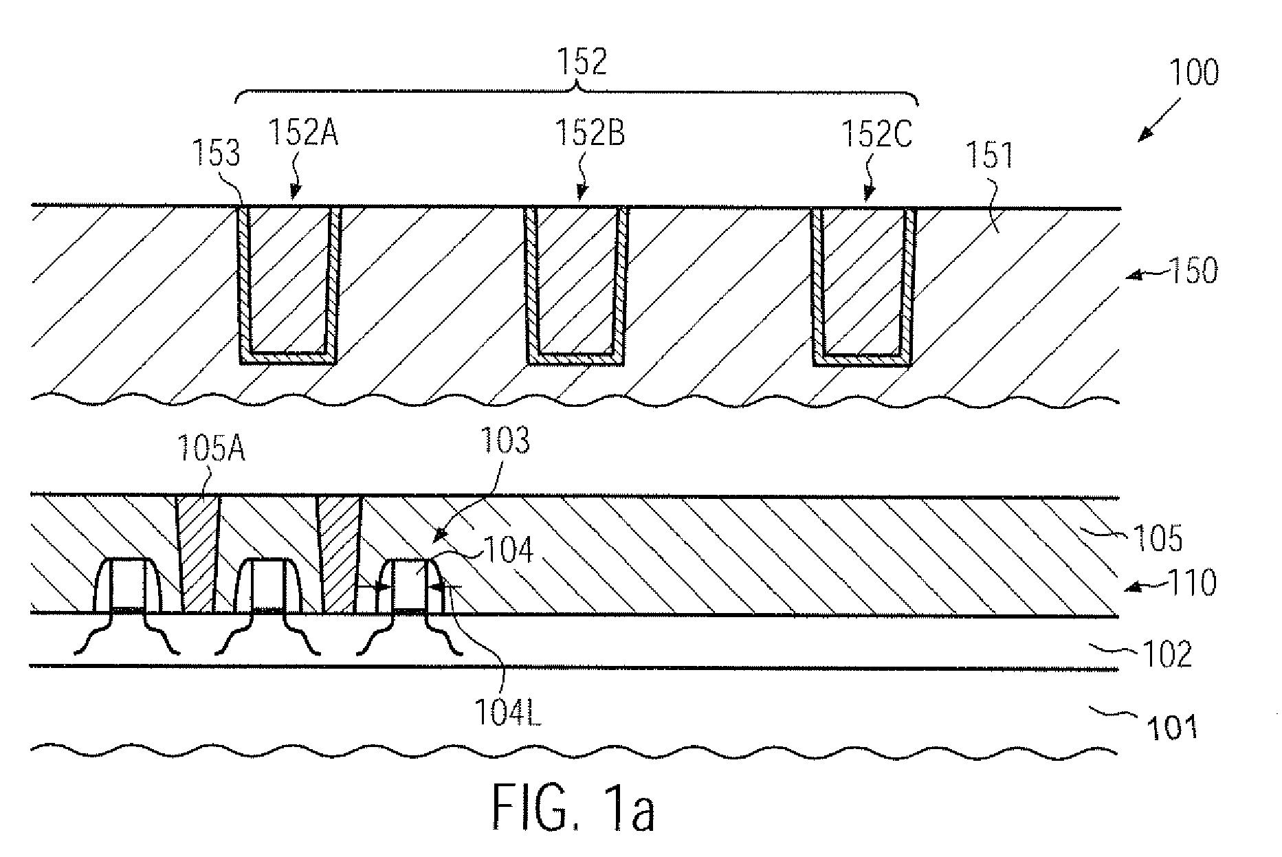
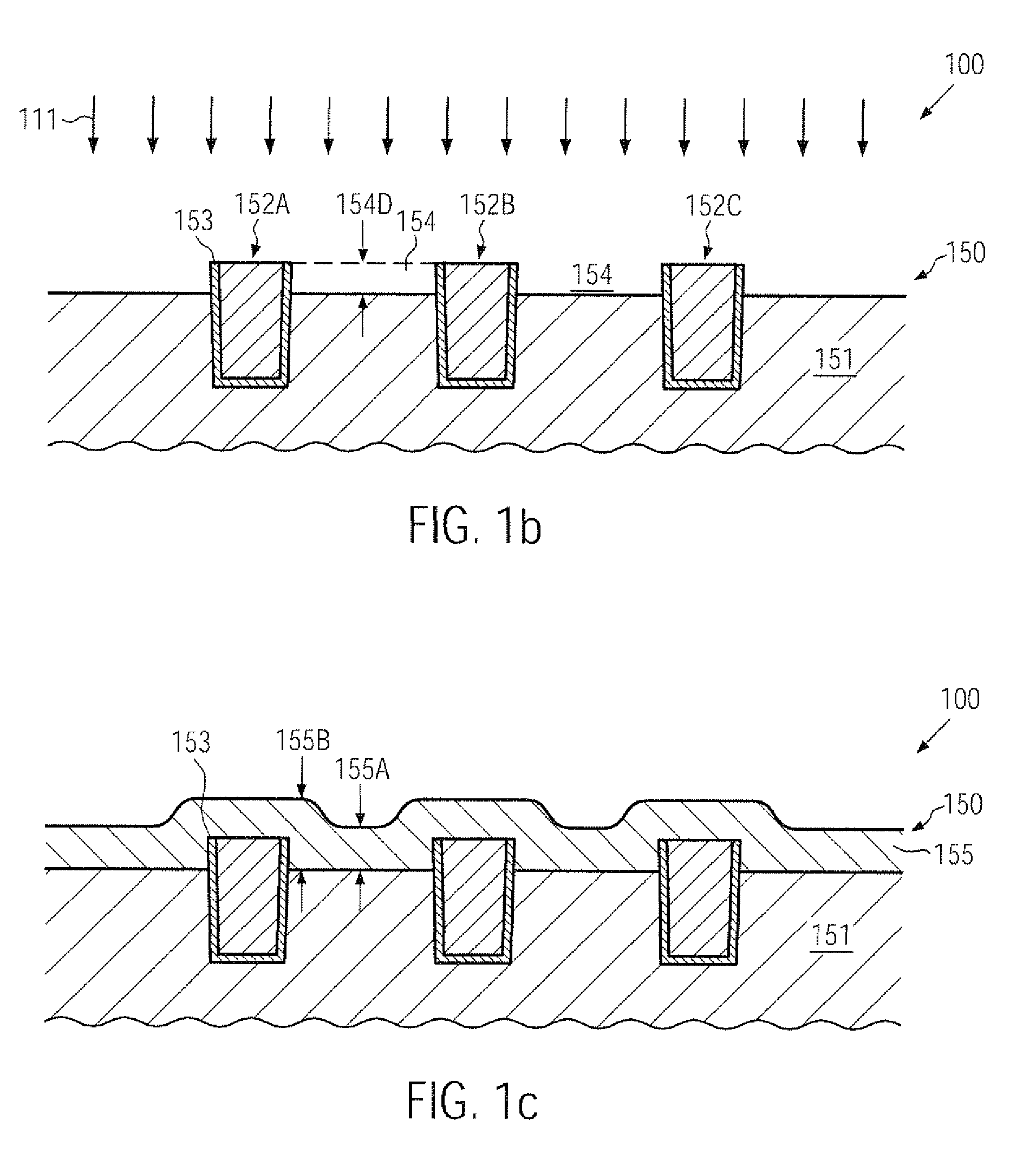
[0013]Generally, the present disclosure relates to methods and devices in which air gaps may be positioned between closely spaced metal regions with sub-lithography resolution, thereby enabling the reduction of the overall permittivity in a reliable and reproducible manner while avoiding cost-intensive sophisticated lithography processes. For this purpose, a positioning and dimensioning of the respective air gaps to be formed in a dielectric material of a metallization level may be accomplished on the basis of deposition and etch processing without applying critical lithography techniques, while also providing a high degree of flexibility in varying the size of the air gaps. In some illustrative aspects disclosed herein, critical device areas in the metallization level may be selected for receiving air gaps, while other device areas may be covered by an appropriate mask, which may, however, be formed on the basis of uncritical process conditions. Consequently, appropriate dielectric materials providing the desired characteristics may be used, while the reliable and reproducible formation of the air gaps at critical device areas in the metallization level may enable an adjustment of the overall permittivity in accordance with device requirements. For example, the metallization levels of integrated circuits including circuit elements of critical dimensions of 40 nm and less may be manufactured with a reduced permittivity, at least locally, while, in total, the mechanical integrity of the metallization level may be enhanced by avoiding extremely sophisticated and critical low-k dielectric materials.

Problems solved by technology

In integrated circuits having minimum dimensions of approximately 0.35 μm and less, a limiting factor of device performance is the signal propagation delay caused by the switching speed of the transistor elements.
For example, copper may not be deposited in relatively high amounts in an efficient manner by well-established deposition methods, such as chemical and physical vapor deposition.
Moreover, copper may not be efficiently patterned by well-established anisotropic etch processes.
Moreover, the diffusion of moisture and oxygen into the copper-based metal has to be suppressed as copper readily reacts to form oxidized portions, thereby possibly deteriorating the characteristics of the copper-based metal line with respect to adhesion, conductivity and the resistance against electromigration.
For example, during CMP processes, a significant degree of mechanical stress may be applied to the metallization levels formed so far, which may cause structural damage to a certain degree, in particular when sophisticated dielectric materials of reduced permittivity are used.
As previously explained, the capacitive coupling between neighboring metal lines may have a significant influence on the overall performance of the semiconductor device, in particular in metallization levels, which are substantially “capacitance driven,” i.e., in which a plurality of closely spaced metal lines have to be provided in accordance with device requirements, thereby possibly causing signal propagation delay and signal interference between neighboring metal lines.
On the other hand, typically, a reduced permittivity of the dielectric material is associated with a reduced mechanical stability, which may require sophisticated patterning regimes so as to not unduly deteriorate reliability of the metallization system.
The continuous reduction of the feature sizes, with gate lengths of approximately 40 nm and less, may demand even more reduced dielectric constants of the corresponding dielectric materials, which may increasingly contribute to yield loss due to, for instance, insufficient mechanical stability of respective ultra low-k materials.
In this case, however, additional cost-intensive lithography steps may be required, wherein the positioning and the dimensioning of the corresponding air gaps may also be restricted by the capabilities of the respective lithography processes.
Since typically in critical metallization levels the lateral dimensions of metal lines and the spacing between adjacent metal lines may be defined by critical lithography steps, an appropriate and reliable manufacturing sequence for providing intermediate air gaps may be difficult to be achieved on the basis of the available lithography techniques.

Method used


Image

  • Microstructure device including a metallization structure with self-aligned air gaps between closely spaced metal lines
  • Microstructure device including a metallization structure with self-aligned air gaps between closely spaced metal lines
  • Microstructure device including a metallization structure with self-aligned air gaps between closely spaced metal lines

Examples


Embodiment Construction

[0026]Various illustrative embodiments of the invention are described below. In the interest of clarity, not all features of an actual implementation are described in this specification. It will of course be appreciated that in the development of any such actual embodiment, numerous implementation-specific decisions must be made to achieve the developers' specific goals, such as compliance with system-related and business-related constraints, which will vary from one implementation to another. Moreover, it will be appreciated that such a development effort might be complex and time-consuming, but would nevertheless be a routine undertaking for those of ordinary skill in the art having the benefit of this disclosure.

[0027]The present subject matter will now be described with reference to the attached figures. Various structures, systems and devices are schematically depicted in the drawings for purposes of explanation only and so as to not obscure the present disclosure with details ...


PUM


Abstract

Air gaps may be provided in a self-aligned manner with sub-lithography resolution between closely spaced metal lines of sophisticated metallization systems of semiconductor devices by recessing the dielectric material in the vicinity of the metal lines and forming respective sidewall spacer elements. Thereafter, the spacer elements may be used as an etch mask so as to define the lateral dimension of a gap on the basis of the corresponding air gaps, which may then be obtained by depositing a further dielectric material.

Description

BACKGROUND OF THE INVENTION[0001]1. Field of the Invention[0002]Generally, the subject matter of the present disclosure relates to microstructure devices, such as integrated circuits, and, more particularly, to the metallization layers including highly conductive metals, such as copper, embedded into a dielectric material of reduced permittivity.[0003]2. Description of the Related Art[0004]In modern integrated circuits, minimum feature sizes, such as the channel length of field effect transistors, have reached the deep sub-micron range, thereby steadily increasing performance of these circuits in terms of speed and / or power consumption and / or diversity of circuit functions. As the size of the individual circuit elements is significantly reduced, thereby improving, for example, the switching speed of the transistor elements, the available floor space for interconnect lines electrically connecting the individual circuit elements is also decreased. Consequently, the dimensions of these...

Claims


Application Information

Patent Timeline
Patent Type & Authority Applications(United States)
IPC IPC(8): H01L23/58H01L21/764
CPCH01L21/76885H01L21/7682H01L21/76834
Inventor FEUSTEL, FRANKWERNER, THOMASFROHBERG, KAI
Owner ADVANCED MICRO DEVICES INC
Learn More