Eureka AIR delivers breakthrough ideas for toughest innovation challenges, trusted by R&D personnel around the world.

Engine exhaust cooler and air pre-cleaner aspirator

a technology of engine exhaust cooler and aspirator, which is applied in the field of aspirators, can solve the problems of significant increase in the temperature of the exhaust, the clogging of the filter alone, etc., and achieve the effect of significant elevation of the temperatur

Active Publication Date: 2009-12-03
DEERE & CO
View PDF16 Cites 7 Cited by
  • Summary
  • Abstract
  • Description
  • Claims
  • Application Information

AI Technical Summary

Benefits of technology

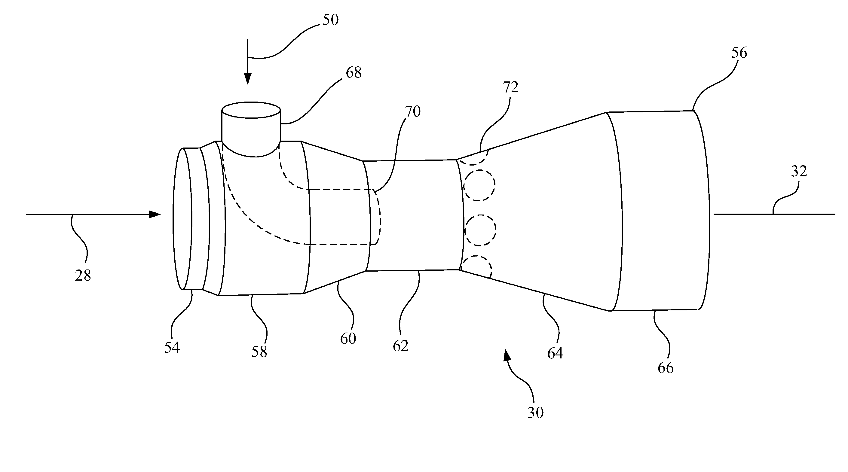
[0007]In another form the invention is an internal combustion engine system having an air breathing, fuel consuming internal combustion engine with an air intake and an exhaust for products of combustion. An exhaust aftertreatment system receiving the products of combustion generates periodic, significantly elevated temperatures. An air filtration system including a pre-cleaner is fluidly connected to and upstream of the engine air intake, the pre-cleaner preventing flow of larger contaminants into the engine air intake and accumulates such contaminants, the pre-cleaner having an outlet for such contaminants. An element defining a primary fluid flow path for engine exhaust from said exhaust aftertreatment system has a venturi section. A tube has an outlet within the element and adjacent the venturi section, the two being fluidly connected to the pre-cleaner outlet for contaminants so that contaminants and ambient air are drawn into and through the tube to cool the exhaust. The element has at least one inlet for ambient air for further cooling the engine exhaust.
[0008]In another form, the invention is a work machine operating in a si

Problems solved by technology

It is necessary for such machines to have a pre-cleaner since the ambient level of contaminant is so significant.
A filter alone would quickly become clogged.
The process of cleaning such particles, commonly referred to as regeneration, causes a significant increase in the temperature of the exhaust, reaching levels as high as 600° C. This elevated temperature represents a potential problem in the contaminated environment of the work.

Method used


Image

  • Engine exhaust cooler and air pre-cleaner aspirator
  • Engine exhaust cooler and air pre-cleaner aspirator
  • Engine exhaust cooler and air pre-cleaner aspirator

Examples


Embodiment Construction

[0012]Referring to FIG. 1, there is shown a portion of a work machine 10 in the form of an agricultural vehicle, particularly the rear end drive train of the vehicle. Although shown as an agricultural vehicle it is possible the work machine 10 could be in the form of a different type of work machine such as a construction or forestry vehicle.

[0013]Work machine 10 includes a transmission 12 providing motive power to the work machine 10 as well as power agriculture crop harvesting and processing components as well as various hydraulic accessory devices. Transmission 12 is powered by an air breathing fuel consuming internal combustion engine, generally shown at 14. Internal combustion engine 14 exhausts the products of combustion to an exhaust line 16 extending to a turbine 18 which drives a compressor 20 through a mechanical interconnection 22. The exhaust from turbine 18 passes through line 24 to an exhaust aftertreatment device 26.

[0014]Exhaust aftertreatment device 26 may incorpora...


PUM

PropertyMeasurementUnit
Temperatureaaaaaaaaaa
Angleaaaaaaaaaa
Flow rateaaaaaaaaaa

Abstract

A diffuser for a work machine having an air breathing fuel consuming internal combustion engine with an exhaust aftertreatment device periodically elevating the exhaust temperatures to a high level. The diffuser has a venturi section and the excess contaminants from an intake air pre-cleaner are directed to the throat of the venturi to aspirate and dispose of excess contaminants while cooling the exhaust flow. Additional openings in the divergent section of the diffuser assist in providing significant reductions in exhaust temperatures within a short axial envelope.

Description

FIELD OF THE INVENTION[0001]The invention relates to aspirators for air cleaning systems, and more specifically, to aspirators used with internal combustion engines.BACKGROUND OF THE INVENTION[0002]The class of work machines utilized for agricultural, industrial and other uses, termed as work machines, typically operates in a highly contaminated environment, thus making the function of cleaning air used by an air breathing internal combustion engine, especially important. Nowhere is this as important as in the agricultural field where the work machine is in a field harvesting crops which generates significant contaminants in the form of chaff and dust. It is necessary for such machines to have a pre-cleaner since the ambient level of contaminant is so significant. A filter alone would quickly become clogged.[0003]In the present environment, pre-cleaners are employed upstream of the primary filter for the intake system of the engine. Such pre-cleaners take various forms, but as used ...

Claims


Application Information

Patent Timeline
IPC IPC(8): F02M35/02
CPCB01D46/4281F01N2470/30F02M35/02F02M35/022Y10S55/28F02M35/10013F02M35/164Y10S55/30F02M35/08
Inventor SCHINDLER, RODNEY A.SHEIDLER, ALAN D.
Owner DEERE & CO
Why Eureka
Eureka Blog
Learn More