
Method of growing silicon single crystals

a single crystal, silicon technology, applied in the direction of crystal growth process polycrystalline material growth, etc., can solve the problems of reducing product yield relative to silicon raw materials, affecting productivity, and reducing yield, so as to reduce tail portion length and inhibit dislocation , the effect of increasing productivity

Inactive Publication Date: 2009-12-03
SUMCO CORP
View PDF7 Cites 8 Cited by
  • Summary
  • Abstract
  • Description
  • Claims
  • Application Information

AI Technical Summary

Benefits of technology

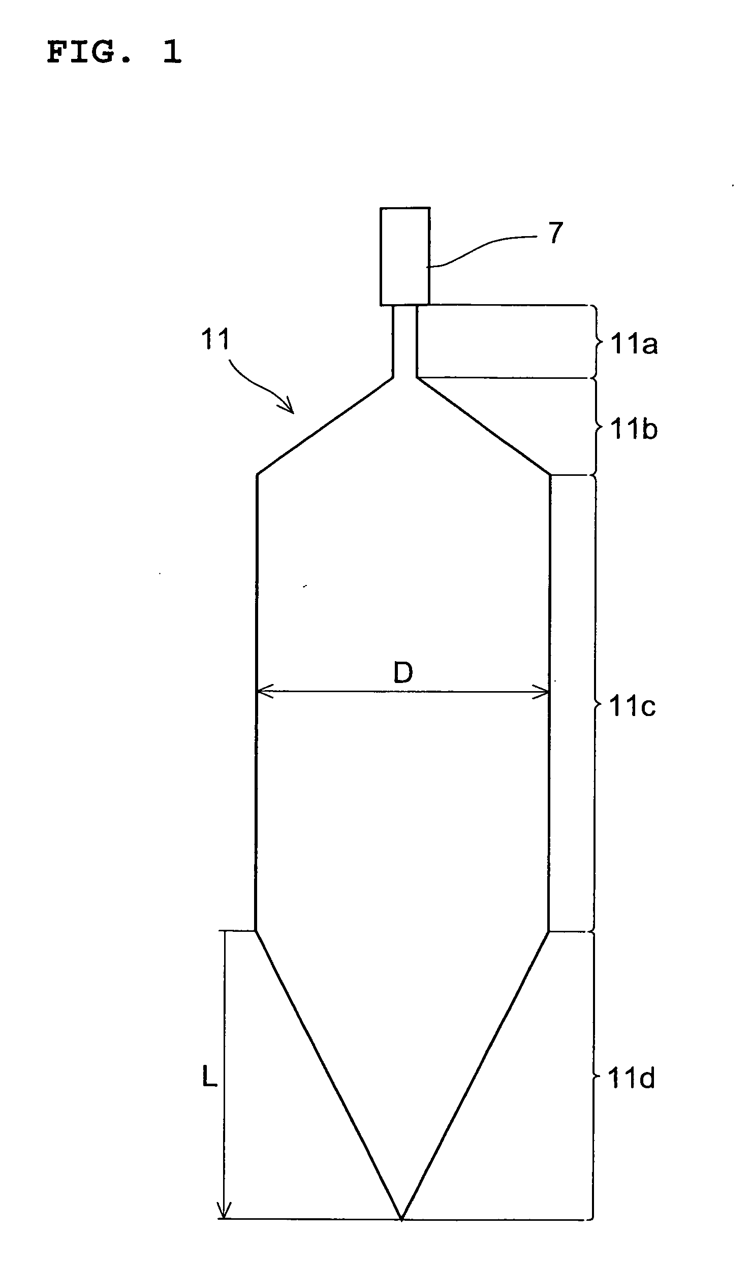
[0010]However, in the case of growing silicon single crystals having a cylindrical body portion with a diameter of 450 mm (hereinafter also referred to as “silicon single crystals having a diameter of 450 mm” for short), the tail portion will have a length of not less than 450 mm when the tail portion is formed under the conventional operation conditions mentioned above, or will have a length exceeding 225 mm even when the tail portion is formed under the conditions proposed in the above-cited Japanese Patent Application Publication No. 2007-284313. Thus, the tail portion becomes elongated in either case. Accordingly, the cylindrical body portion, the product, of each silicon single crystal is shortened, raising such problems as reduction in product yield relative to the silicon raw materials and hindrance to improvement in productivity.
[0011]In this regard, the reduction in yield may be prevented and the productivity may be improved if the tail portion length is reduced; however, this may possibly cause the occurrence of dislocations during the formation of the tail portion.
[0012]The present invention has been made in view of such situations as mentioned above, and an object thereof is to provide a method of growing silicon single crystals according to which method the occurrence of dislocations can be inhibited and improvements of yield and productivity can be achieved by specifying the tail portion length in growing silicon single crystals having a diameter of 450 mm by the CZ method.
[0014]On the occasion of tail portion formation, adjustments are generally made to raise the temperature of the silicon melt (hereinafter referred to as “melt temperature”) and, at the same time, increase the speed of pulling up the silicon single crystal (hereinafter referred to as “pulling speed”); when the increase in melt temperature and / or pulling speed is too sharp, however, dislocations may occur at the crystal growth interface or, in some cases, the tail portion may be detached from the silicon melt during tail portion formation, resulting in occurrence of dislocations. When, on the contrary, the tail portion to be formed is surely given a length of 100 mm or more, the melt temperature and pulling speed can be controlled without any abrupt change and the tail portion gradually reduced in diameter can be formed and, as a result, dislocations can be inhibited from occurring.
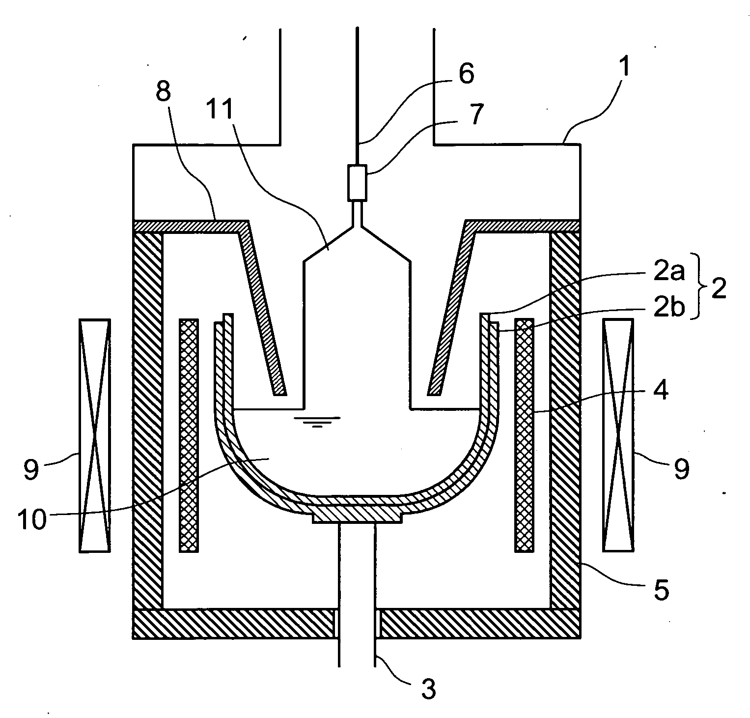
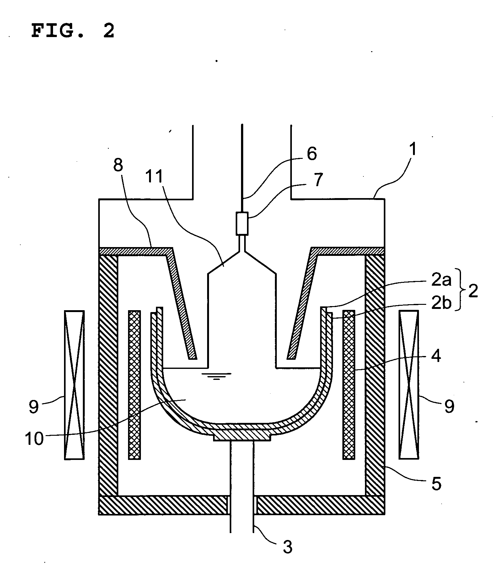
[0015]For inhibiting dislocations from occurring more effectively on the occasion of tail portion formation, it is effective to apply a transverse magnetic field to the silicon melt. The application of such a transverse magnetic field inhibits the convection of the silicon melt and suppress abrupt change in melt temperature at the crystal growth interface, so that the tail portion is likely formed in a manner such that the diameter thereof is reduced gradually.
[0019]In accordance with the method of growing silicon single crystals according to the present invention, it is possible to form a tail portion gradually reduced in diameter on the occasion of growing silicon single crystals having a diameter of 450 mm by the CZ method by specifying the tail portion length at a level of 100 mm or more and, as a result, it becomes possible to inhibit dislocations from occurring in the tail portion. In addition, the tail portion length can be reduced as compared with the case of tail portion formation under the conventional operation conditions or the conditions proposed by Japanese Patent Application Publication No. 2007-284313; thus, it becomes possible to achieve a yield improvement and increase productivity.

Problems solved by technology

Accordingly, the cylindrical body portion, the product, of each silicon single crystal is shortened, raising such problems as reduction in product yield relative to the silicon raw materials and hindrance to improvement in productivity.
In this regard, the reduction in yield may be prevented and the productivity may be improved if the tail portion length is reduced; however, this may possibly cause the occurrence of dislocations during the formation of the tail portion.

Method used


Image

  • Method of growing silicon single crystals
  • Method of growing silicon single crystals
  • Method of growing silicon single crystals

Examples


examples

[0035]For confirming the effects of the method of growing silicon single crystals according to the present invention, a numerical analysis was carried out if dislocations should occur or not. The case assumed in the numerical analysis was such that a crucible having an inside diameter of 40 inches was used in the single crystal pulling apparatus shown in FIG. 2, a transverse magnetic field of 0.1 T was applied, and silicon single crystals having a total weight of 1000 kg and a diameter of 450 mm were grown. The numerical analysis was carried out under such conditions that the tail portion length was varied as follows: 50 mm, 80 mm, 100 mm, 200 mm and 500 mm.

[0036]As a result, the occurrence of dislocations was appreciated when the tail portion length was 50 mm or 80 mm, whereas no occurrence of dislocations was found when the tail portion length was 100 mm, 200 mm or 500 mm. Thus, it can be said that when the tail portion length is not less than 100 mm in growing silicon single crys...


PUM

PropertyMeasurementUnit
lengthaaaaaaaaaa
diameteraaaaaaaaaa
transverse magnetic fieldaaaaaaaaaa

Abstract

By providing a length of not less than 100 mm to a tail portion to be formed following the cylindrical body portion in growing silicon single crystals having a cylindrical body portion with a diameter of 450 mm using the CZ method, it becomes possible to inhibit the occurrence of dislocations in the tail portion and thus achieve improvements in yield and productivity. A transverse magnetic field having an intensity of not less than 0.1 T is preferably applied on the occasion of formation of that tail portion.

Description

BACKGROUND OF THE INVENTION[0001]1. Field of the Invention[0002]The present invention relates to a method of growing silicon single crystals using the Czochralski method (hereinafter referred to as “CZ method”) and, more particularly, to a method of growing silicon single crystals which is suited for growing large-diameter silicon single crystals having a cylindrical body portion with a diameter of 450 mm.[0003]2. Description of the Related Art[0004]Silicon single crystals are source materials for manufacturing silicon wafers to be used in semiconductor devices, and single crystal growing processes based on the CZ method are in wide use for the production thereof. According to the CZ method, silicon single crystals are generally grown in the following manner.[0005]In a pulling apparatus in which an inert gas atmosphere is maintained under reduced pressure, silicon raw materials placed in a quartz crucible are heated and melted by means of a heater, and a seed crystal is immersed int...

Claims


Application Information

Patent Timeline
Patent Type & Authority Applications(United States)
IPC IPC(8): C30B15/22
CPCC30B15/22C30B30/04C30B29/06C30B15/305
Inventor TSURUMARU, TAKANORIHARA, HIDEKIKAITO, RYOICHI
Owner SUMCO CORP
Learn More