
Computer-guided system for orienting the acetabular cup in the pelvis during total hip replacement surgery

a technology of acetabular cup and computer guided surgery, which is applied in the field of computer guided surgery, can solve the problems of difficult interoperative detection, increased procedure cost, and difficulty in acquiring one or more pelvic anatomical landmarks, and achieve the effect of reducing the impingement and dislocation problems

Inactive Publication Date: 2009-11-26
THORNBERRY ROBERT L
View PDF17 Cites 44 Cited by
  • Summary
  • Abstract
  • Description
  • Claims
  • Application Information

AI Technical Summary

Benefits of technology

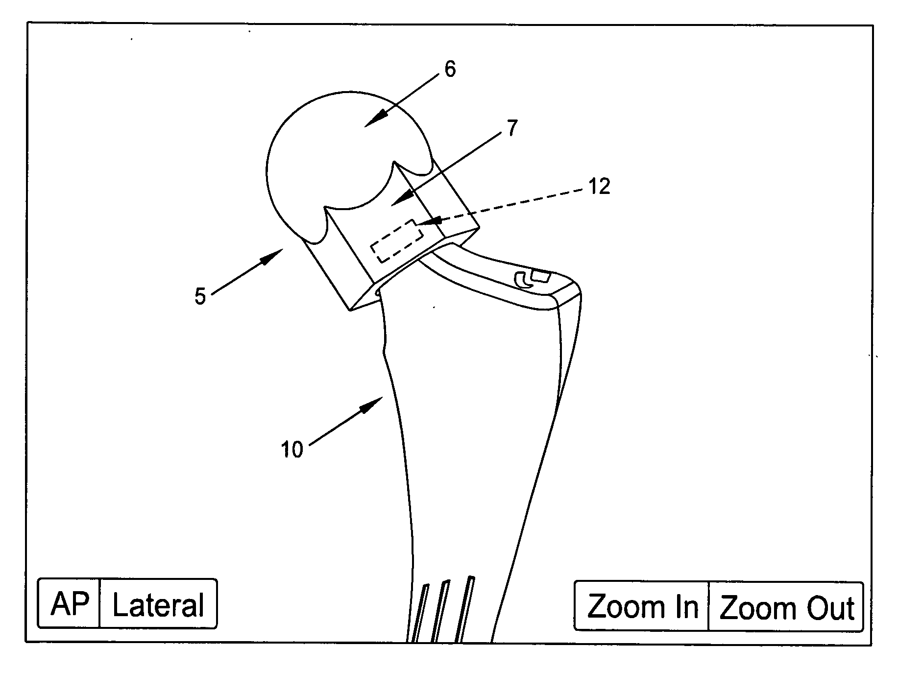
[0021]More particularly, with the present invention, the surgeon first sets the prosthetic acetabular cup into the pelvis in the conventional manner (e.g., “by eye”). The surgeon then uses the new computer-guided system of the present invention to: (i) detect the current spatial relationship between the acetabular cup and the femur using kinematic action; (ii) compare the current spatial relationship between the acetabular cup and the femur to the desired (i.e., “ideal”) spatial relationship between the acetabular cup and the femur (e.g., so as to minimize the aforementioned impingement and dislocation problems); and (iii) adjust the current orientation of the acetabular cup with a device so as to set the acetabular cup with the desired orientation.

Problems solved by technology

However, this approach relies heavily on the anatomical view available to, and appreciated by, the surgeon, and errors in cup orientation (i.e., tilt) may not be discovered until after the surgery has been completed, since such errors in cup orientation can be difficult to detect interoperatively, even with the use of X-rays.
However, in practice, one or more of these pelvic anatomical landmarks can be difficult to acquire.
These requirements can add to the cost of the procedure, can lengthen the time required for the procedure, and can be inconvenient for the surgeon (e.g., such as where the surgeon must work around optical trackers protruding into the surgical field).

Method used


Image

  • Computer-guided system for orienting the acetabular cup in the pelvis during total hip replacement surgery
  • Computer-guided system for orienting the acetabular cup in the pelvis during total hip replacement surgery
  • Computer-guided system for orienting the acetabular cup in the pelvis during total hip replacement surgery

Examples


Embodiment Construction

[0049]The present invention comprises a new and improved computer-guided system for orienting the acetabular cup in the pelvis during total hip replacement surgery, wherein the requirement for a pre-operative CT scan is eliminated (but may still be provided if desired), and wherein the requirement for the acquisition of pelvic landmarks is eliminated (but may still be provided if desired).

[0050]More particularly, with the present invention, the surgeon first sets the prosthetic acetabular cup into the pelvis in the conventional manner (e.g., “by eye”). The surgeon then uses the new computer-guided system of the present invention to: (i) detect the current spatial relationship between the acetabular cup and the femur using kinematic action; (ii) compare the current spatial relationship between the acetabular cup and the femur to the desired (i.e., “ideal”) spatial relationship between the acetabular cup and the femur (e.g., so as to minimize the aforementioned impingement and disloca...


PUM


Abstract

A method for determining the orientation of a first object in space, wherein the first object is interactive with a second object, the method comprising the steps of:using kinematic action to generate a first data set reflective of the current spatial relationship between the first object and the second object; andcomparing the first data set with a database of known data sets reflective of known spatial relationships between the first object and the second object in space so as to identify the current orientation of the first object in space.

Description

REFERENCE TO PENDING PRIOR PATENT APPLICATIONS[0001]This patent application:[0002](i) claims benefit of pending prior U.S. Provisional Patent Application Ser. No. 61 / 069,267, filed Mar. 13, 2008 by Robert C. Thornberry for COMPUTER-GUIDED SYSTEM FOR ORIENTING THE ACETABULAR CUP IN THE ACETABULUM DURING TOTAL HIP REPLACEMENT SURGERY (Attorney's Docket No. TBERRY-1 PROV); and[0003](ii) claims benefit of pending prior U.S. Provisional Patent Application Ser. No. 61 / 134,994, filed Jul. 16, 2008 by Robert C. Thornberry for COMBINED USE OF SIMULATION AND NAVIGATION TO DEMONSTRATE HIP KINEMATICS (Attorney's Docket No. TBERRY-2 PROV).[0004]The two above-identified patent applications are hereby incorporated herein by reference.FIELD OF THE INVENTION[0005]This invention relates to computer-guided surgery in general, and more particularly to computer-guided surgery for orienting the acetabular cup in the pelvis during total hip replacement surgery.BACKGROUND OF THE INVENTION[0006]Joint replac...

Claims


Application Information

Patent Timeline
IPC IPC(8): A61F2/32G08B1/00
CPCG06T7/0048G06T2207/10028G06F17/5009A61F2/34G06T2207/30008G06T7/77G06F30/20
Inventor THORNBERRY, ROBERT L.
Owner THORNBERRY ROBERT L
Learn More