Automobile Bumper Back Beam Structure

Inactive Publication Date: 2009-11-26
HYUNDAI MOTOR CO LTD
View PDF7 Cites 9 Cited by
  • Summary
  • Abstract
  • Description
  • Claims
  • Application Information

AI Technical Summary

Benefits of technology

[0016]Various embodiments of the present invention are directed at providing an automobile bumper back beam structure comprising a guide member for preventing under-riding in the bumper back beam so as to adjust a height difference of automobiles in collision of the automobiles, thereby remarkably reducing a shock from the collision, a damaged area and repair cost of the damage.
[0017]According to an exemplary embodiment of the present invention, an automobile bumper back beam structure provided in a bumper cover may comprise a guide member provided on a bumper back beam and positioned between the bumper cover and the bumper back beam, the guide member supporting the bumper cover elastically and preventing under-riding from being generated when vehicles collide.

Problems solved by technology

However, when automobiles whose heights are different from each other collide at a low speed, under-riding occurs due to the difference of the heights of the automobiles.
As a result, a damaged part of the automobile can become enlarged to cause excessive repair cost.
However, the conventional reinforce member 30 causes the under-riding in collision of automobiles whose heights are different from each other due to lack of overlap.
Also, the reinforce member is manufactured in a large size to increase the manufacturing cost.

Method used


Image

  • Automobile Bumper Back Beam Structure
  • Automobile Bumper Back Beam Structure
  • Automobile Bumper Back Beam Structure

Examples


Embodiment Construction

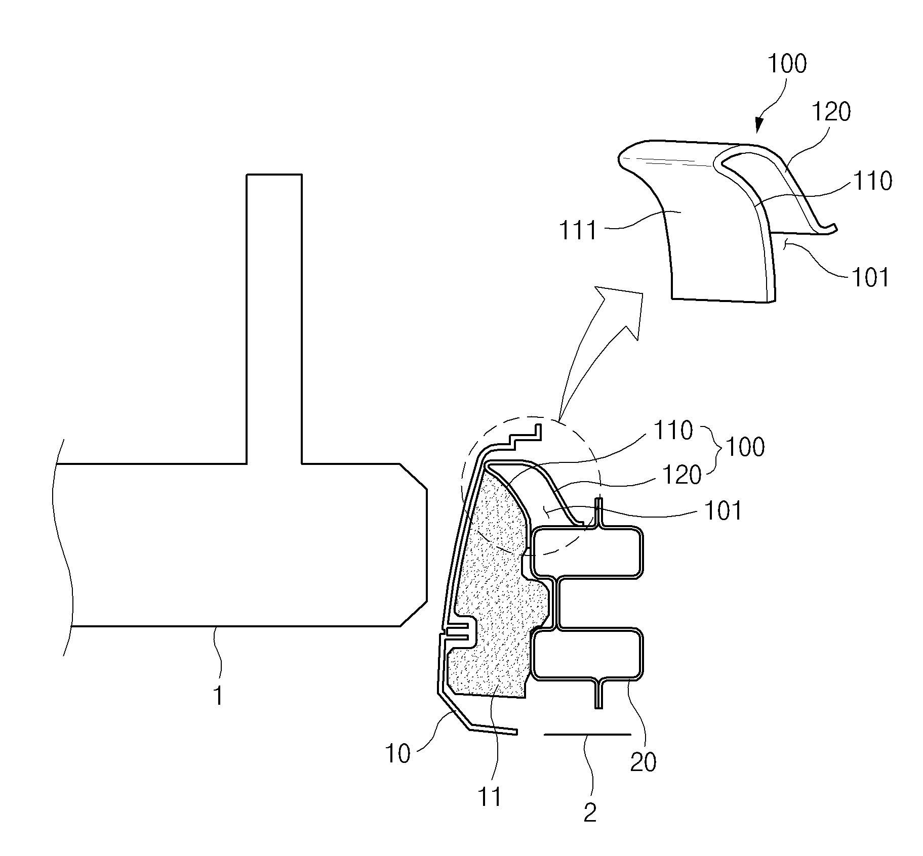
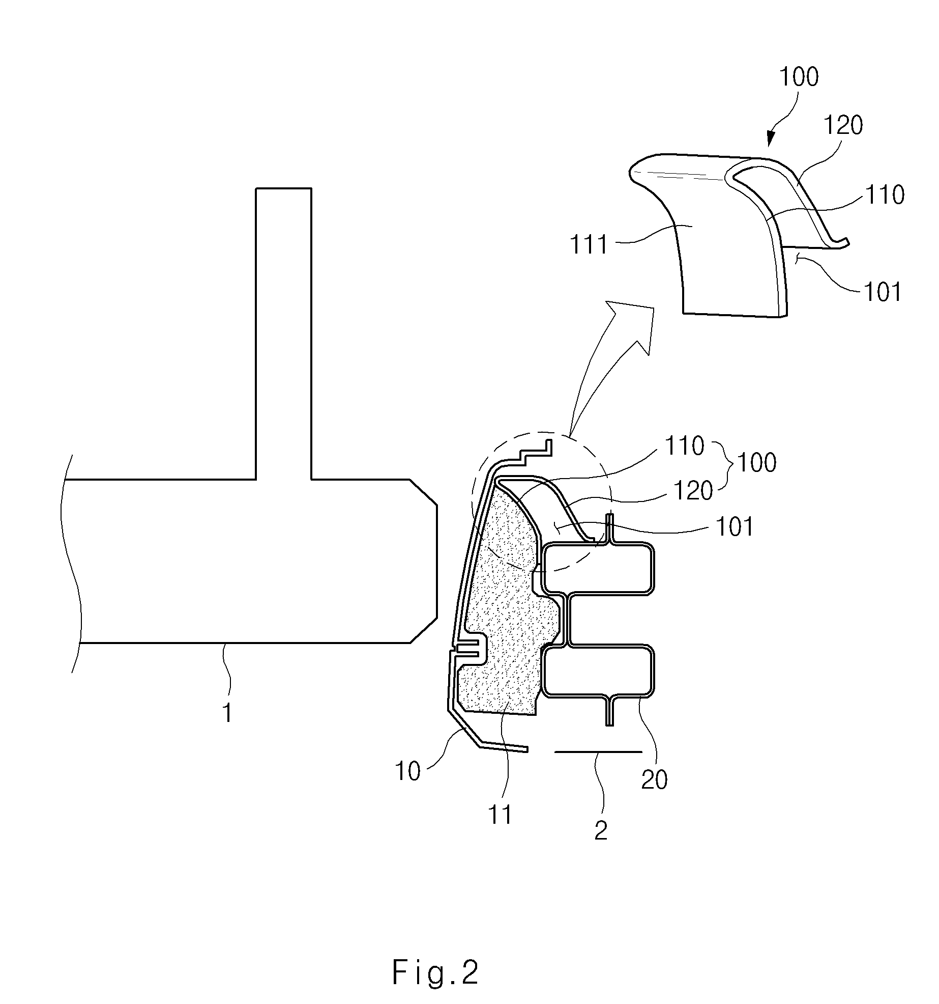
[0026]Hereinafter, an automobile bumper back beam structure according to an embodiment of the present invention will be explained in more detail with reference to FIGS. 2 to 4.

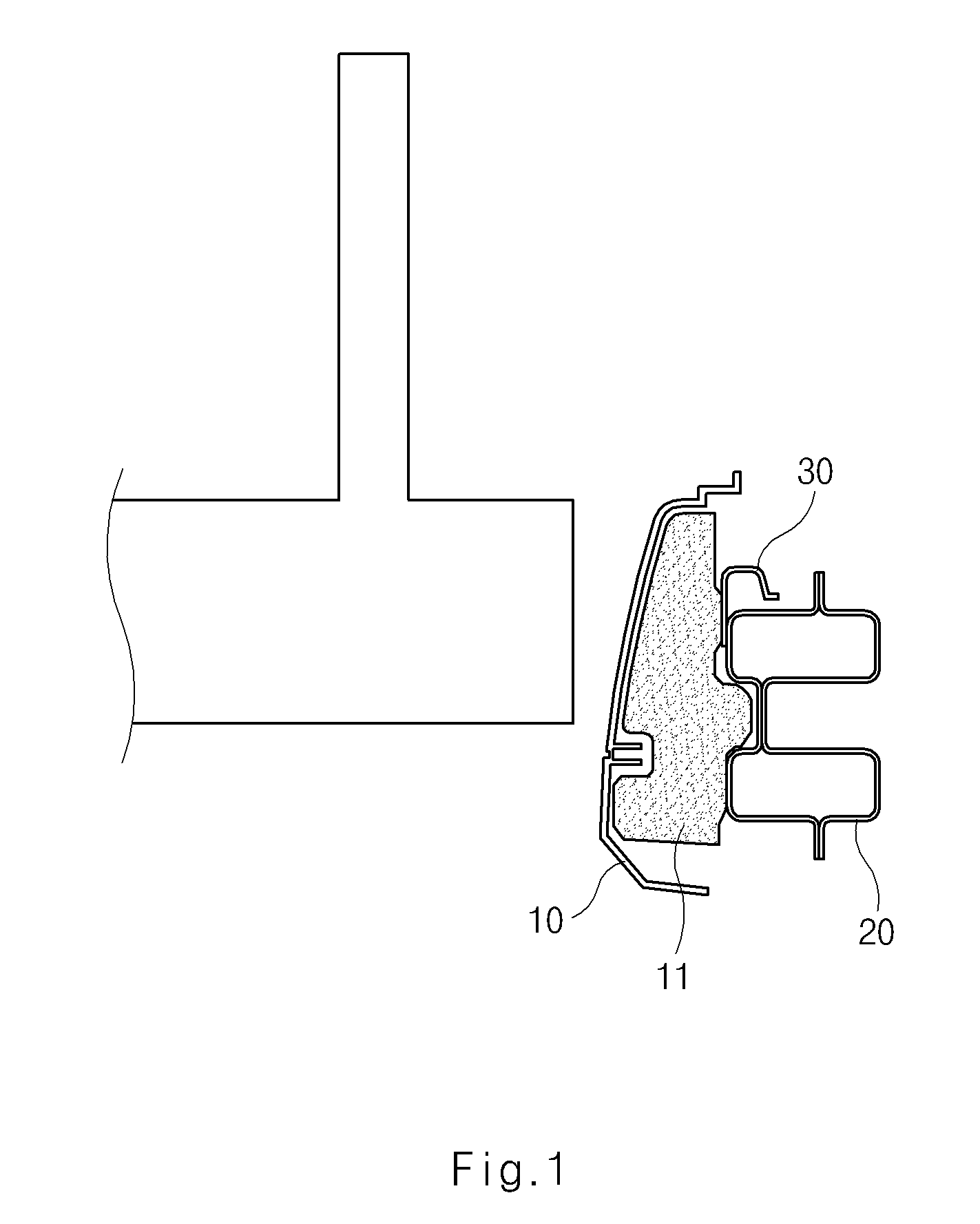
[0027]As shown in FIG. 2, an automobile bumper structure according to an exemplary embodiment of the present invention, which is provided to reduce a shock force and to protect passengers in a collision accident, comprises a bumper cover 10 provided at a front surface and a rear surface of an automobile to form an external housing, a bumper back beam 20 provided in the bumper cover 10 to alleviate the shock force, and a buffering member 11 provided between the bumper cover 10 and the bumper back beam 20 to absorb the shock force.

[0028]In other words, the shock force generated in a collision and passing through the bumper cover 10 is absorbed primarily by the buffering member 11. Then, the shock force is secondarily buffered by the bumper back beam 20, whereby the shock force is remarkably reduced.

[0029]However...


PUM


Abstract

An automobile bumper back beam structure provided in a bumper cover comprises a guide member for preventing under-riding from being generated when vehicles collide. The guide member comprises a guide part which is concavely curved with an arc-shape and fixed at the bumper back beam in the bottom end of the guide part and a supporting part which is extended from the top end of the guide part and fixed at the bumper back beam in the bottom end of the guide part. The guide member for adjusting a height difference of bumpers prevents under-riding of the bumpers when automobiles collide at a low speed, and minimizes a damaged area, thereby reducing repair cost and alleviating shock to obtain stability and silence.

Description

CROSS-REFERENCE TO RELATED APPLICATION[0001]Priority is claimed to Korean Patent Application Number 10-2008-0045814, filed on May 16, 2008, which is incorporated by reference in its entirety.BACKGROUND OF THE INVENTION[0002]The present invention relates to an automobile bumper back beam structure, and more particularly, to an automobile bumper back beam structure comprising a guide member for preventing under-riding in a back beam to induce a stable collision when automobiles whose heights are different from each other collide.[0003]In general, automobile bumpers are installed at the front and rear of an automobile to absorb a shock generated when the automobile collides with another automobile or an external object, thereby reducing the shock applied to the automobile and protecting not only the automobile body but also passengers.[0004]Generally, the automobile bumper comprises a bumper cover and a bumper back beam.[0005]The bumper cover is mounted to the front and the rear of the...

Claims


Application Information

Patent Timeline
IPC IPC(8): B60R19/18B60R19/04
CPCB60R2019/1873B60R19/18B60R19/023B60R19/04B60R2019/026B60R2019/1806
Inventor HEO, SU YOUNG
Owner HYUNDAI MOTOR CO LTD
Why Eureka
Try Eureka