
Double Check Back Flow Prevention Device

Active Publication Date: 2009-11-26
WCM IND INC
View PDF14 Cites 17 Cited by
  • Summary
  • Abstract
  • Description
  • Claims
  • Application Information

AI Technical Summary

Benefits of technology

[0015]It is one aspect of the present invention to provide a double check valve for interconnection to a sill cock associated with an outside water source that prevents back flow into the water supply. Back flow can occur as a result of a siphon condition wherein a vacuum exists within the check valve, the sill cock or the water source that is apt to suction water in a hose, or in the interconnected check valve into the water supply. A back flow condition may also occur when the fluid pressure within the hose is greater than that of the water supply. For example, if the hose was taken to a roof of a building, the resulting head pressure may be greater than the supply pressure. In addition, a temporary loss or interruption in supply pressure may create a pressure differential that would create a back flow situation. The embodiments of the present invention also provide freeze protection wherein water inside the sill cock is allowed to freely drain from the double check valve after supply pressure is removed.
[0017]It is thus another aspect of the present invention to provide a check valve that omits or is devoid of components employed in prior art systems, thus rendering embodiments of the present invention easier and less expensive to manufacture, lighter, less complex, less prone to malfunction, and easier to repair. More specifically, embodiments of the present invention omit additional valves but continue to provide the same functionality of check valves of the prior art, such as the V-444 described above. That is, a system is provided that more effectively employs less than three valves and preferably two valves, thereby allowing size, weight and failure reduction. For example, it is contemplated that the double check valve of embodiments of the present invention are about ⅓ the size (preferably an about 70% reduction) of the V-444 check valve, which reduces bulk, weight and facilitates installation. Preferably, the check valve of one embodiment of the present invention is approximately 1.2 inches in length (an about 44% reduction) and approximately 1.4 inches in diameter (an about 26% reduction) and weighs about 130 grams (an about 35% reduction). In one embodiment, this reduction in size and weight is attributed to the omission of a spool and a stem that controls flow out of the vents of the V-444 check valve. To achieve this, embodiments of the present invention allow for drainage from a point other than through vents in a valve body, for example, drainage from the outlet of the double check valve as opposed to primarily through vents provided in a valve body, as is done by the V-444 check valve. In addition, the present invention employs a fixed inlet valve and a fixed outlet valve as opposed to the complicated valving scheme employed by the V-444, wherein a movable spool alters the configuration of the internal volume of the valve depending on flow condition.

Problems solved by technology

In addition, a temporary loss or interruption in supply pressure may create a pressure differential that would create a back flow situation.

Method used


Image

  • Double Check Back Flow Prevention Device
  • Double Check Back Flow Prevention Device
  • Double Check Back Flow Prevention Device

Examples


Embodiment Construction

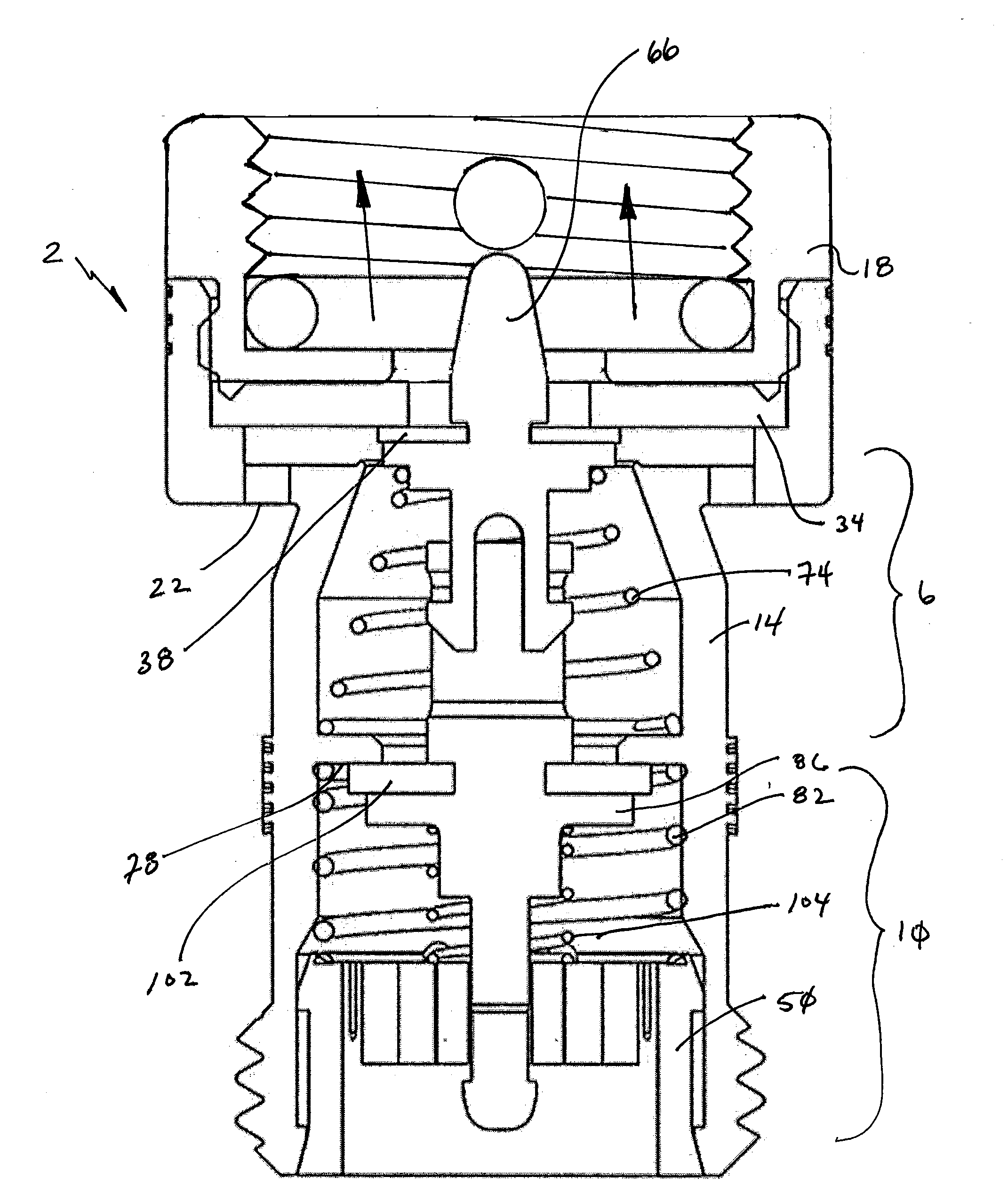
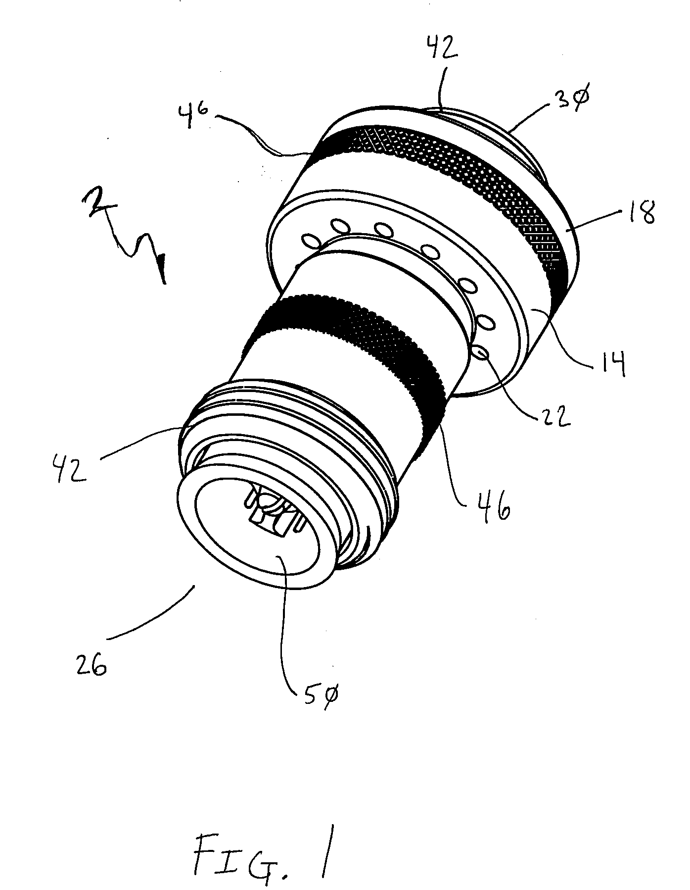
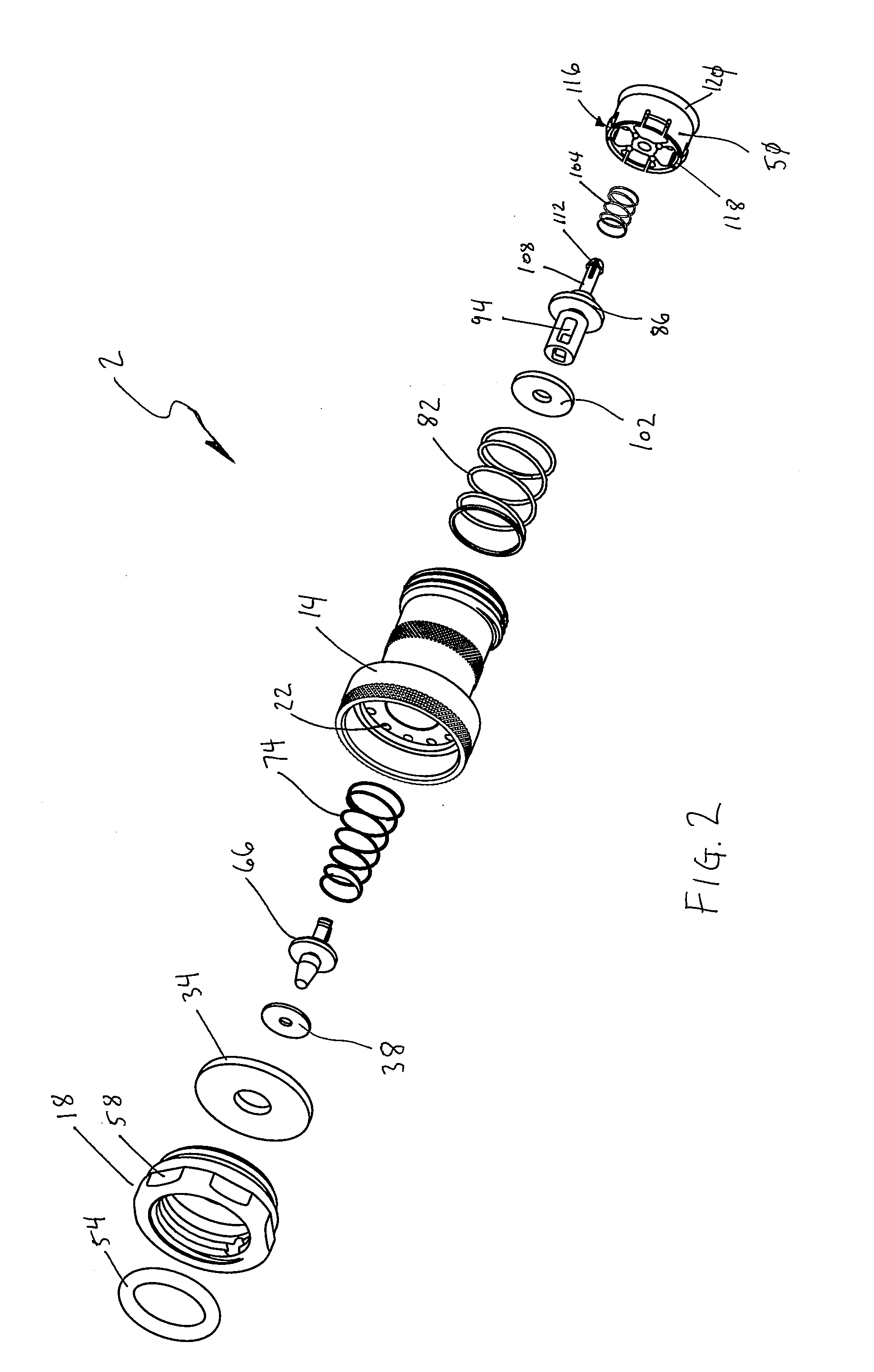
[0042]Referring now to FIGS. 1-12, a double check valve 2 is provided that includes an inlet check valve 6 and an outlet check valve 10 positioned in a valve body 14. The valve body 14 receives a valve cap 18 that is adapted for interconnection to a sill cock of a faucet, for example. The valve body 14 also includes a plurality of vents 22 that allow for drainage of fluids from the sill cock, the inlet check valve 6 and / or outlet check valve 10 depending on the pressure gradient within the double check valve 2. Embodiments of the present invention thus allow fluid within the sill cock to drain from the double check valve to prevent freezing. Back flow is prevented such that when pressure at an outlet 26 of the double check valve is greater than the pressure at the inlet 30, which is in communication with a fluid supply, a main seal 34 (or diaphragm) will cooperate with an inlet check seal 38 to prevent back flow from entering the fluid supply. Excess water then will be trapped withi...


PUM


Abstract

A double check valve is provided that includes an in-line inlet check valve and an outlet check valve that cooperate to prevent back flow of fluid through the valve. The check valve also includes at least one vent that allows for fluid trapped within the check valve to drain, thereby preventing freezing of the check valve and hydrant to which it is interconnected. The check valve provided omits many superfluous components and thus is smaller and easier to install than check valves of the prior art.

Description

FIELD OF THE INVENTION[0001]Embodiments of the present invention are generally related to back flow preventors that interconnect to a water source. More particularly, devices that attach to a sill cock, or any other fluid source, to prevent back flow of fluids, that may contain contaminants into the fluid supply are provided.BACKGROUND OF THE INVENTION[0002]Almost all buildings include some type of exterior fluid delivery system. The most common outdoor fluid delivery system is comprised of a faucet with a handle for actuating a valve that initiates or ceases fluid flow from a fluid source through a sill cock of the faucet. In order to direct the exiting fluid, it is also well known to employ a hose that is threadingly interconnected to the sill cock. Fluid in the hose may, under certain conditions, enter the faucet and ultimately the fluid source. For example, if the fluid pressure in the hose is greater than the fluid supply pressure “back flow” will occur. Such back flow may be h...

Claims


Application Information

Patent Timeline
Patent Type & Authority Applications(United States)
IPC IPC(8): E03B1/00
CPCF16K17/04E03C1/106Y10T137/3331Y10T137/88054Y10T137/7922Y10T137/3149F16K15/066F16K17/048
Inventor BALL, WILLIAM T.PILARCZYK, ERIC
Owner WCM IND INC
Learn More