
Method for Allocating Power to Source and Relay Stations in Two-Hop Amplify-and-Forward Relay Multi-Input-Multi-Output Networks

a relay station and multi-input-multi-output technology, applied in the direction of transmission monitoring, power management, electrical equipment, etc., can solve the problems and achieve the effect of good trade-off between performance and complexity

Inactive Publication Date: 2009-11-19
MITSUBISHI ELECTRIC RES LAB INC
View PDF4 Cites 26 Cited by
  • Summary
  • Abstract
  • Description
  • Claims
  • Application Information

AI Technical Summary

Benefits of technology

[0010]As defined herein, static means that the power allocation method is based on a static path loss, instead of an instantaneous channel state information over the SS to RS and RS to DS channels (hops). Therefore, the method has a good tradeoff between performance and complexity. The method realizes optimal static power allocation in the sense that the method maximizes an upper bound of an average capacity of the two-hop AF relay MIMO network under an average total transmit power constraint.

Problems solved by technology

Therefore, the method has a good tradeoff between performance and complexity.

Method used


Image

  • Method for Allocating Power to Source and Relay Stations in Two-Hop Amplify-and-Forward Relay Multi-Input-Multi-Output Networks
  • Method for Allocating Power to Source and Relay Stations in Two-Hop Amplify-and-Forward Relay Multi-Input-Multi-Output Networks
  • Method for Allocating Power to Source and Relay Stations in Two-Hop Amplify-and-Forward Relay Multi-Input-Multi-Output Networks

Examples


Embodiment Construction

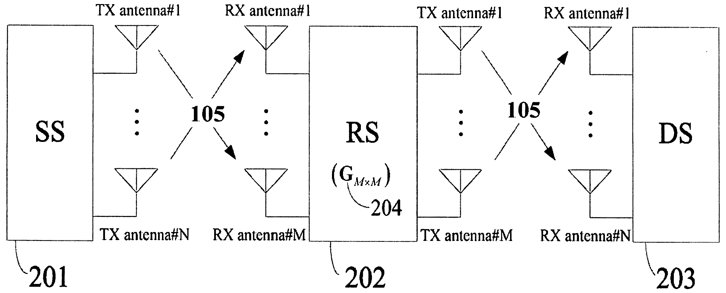
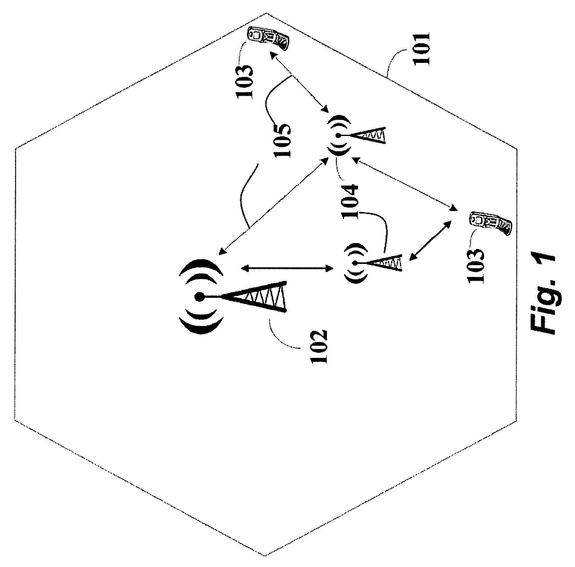
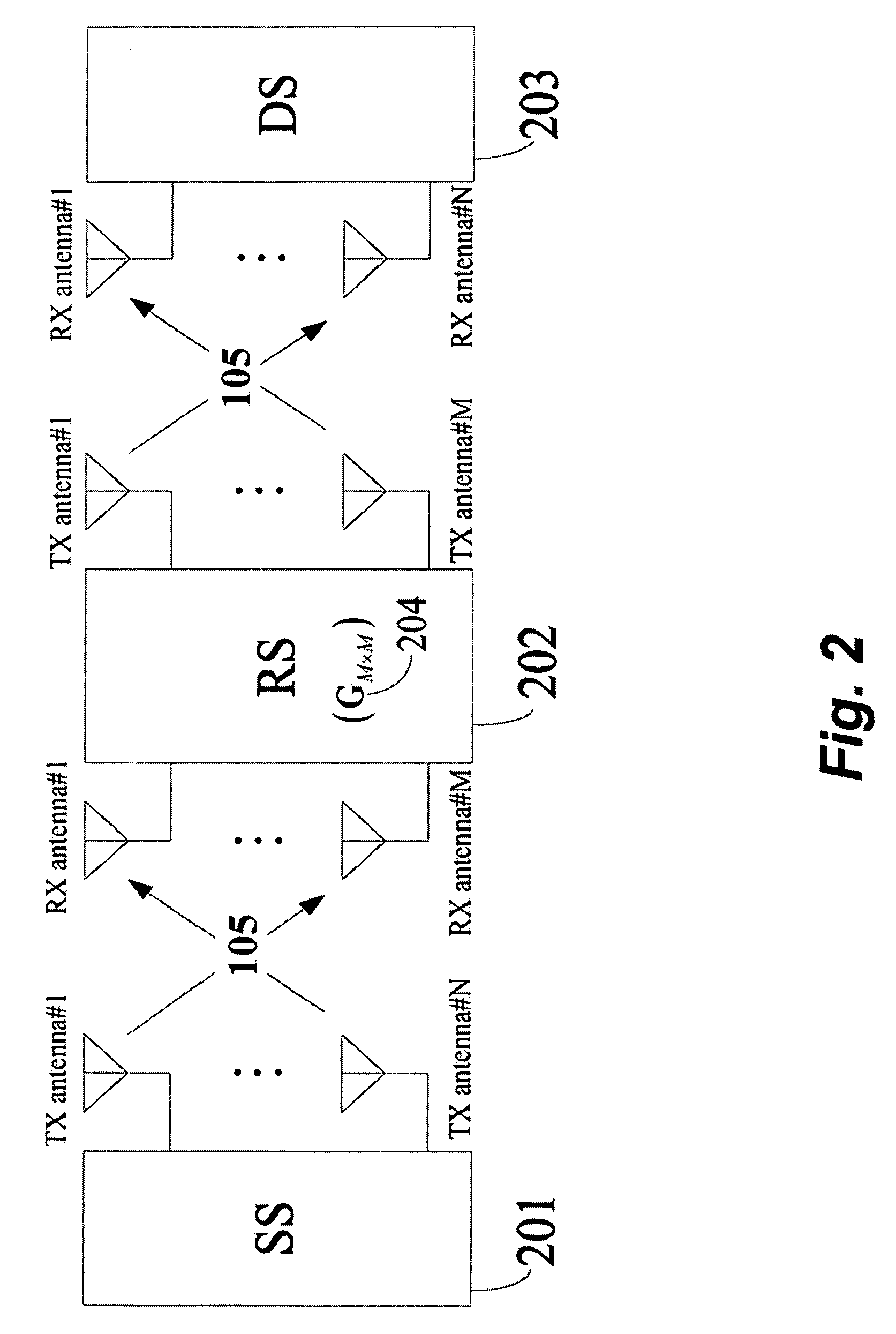
[0014]FIG. 1 shows a two-hop relay cooperative communication network capable with static power allocation to a source station (SS) and a relay station (RS) 104 according to the embodiments of our invention. The network can be a wireless local network, a metropolitan area network, or in a wireless cellular (mobile) network. It could be understood that there can be multiple relay stations.

[0015]In a service area 101, there is one base station (BS) 102, multiple mobile stations (MS) 103 communicating with the BS in parallel, and one or more of the RSs 104. The RSs assist a remote MS to communicate with the BS. The RS can concurrently assist multiple MSs, while each MS only communicates with only one RS at the time. The RS can be fixed, nomadic, or even mobile.

[0016]Depending on a direction of communication, i.e., downlink or uplink, the BS and the mobile stations can operate as the SS or the DS. That is, the communication is considered to be bi-directional between the BS and the MS. Th...


PUM


Abstract

Disclosed is a method for static power allocation to source and relay stations in a two-hop amplify-and-forward (AF) relay multi-input-multi-output (MIMO) network including of a source station (SS), a relay station (RS), and a destination station (DS) each transmitting signals using multiple antennas. The method performs power allocation to the SS and the RS according to the path loss, or equivalently, according to a distances, between the SS and the RS and the RS and DS. The transmit power of each transmit antenna at the SS and the power amplifying gain of the RS are determined from the power allocation outputs.

Description

FIELD OF THE INVENTION[0001]This invention relates generally to relay assisted cooperative communication, and more particularly to allocating power to a source station (SS) and a relay station (RS) in a two-hop amplify-and-forward (AF) relay multi-input-multi-output (MIMO) network.BACKGROUND OF THE INVENTION[0002]Cooperative communication is regarded as one of the critical techniques to be used in next generation wireless communication networks. A typical single-user relay assisted cooperative communication network includes a source station (SS), one or more relay stations (RSs), and a destination station (DS). The RS receives a signal from the SS, performs appropriate signal processing, and then relays the signal to the DS. Relay techniques can increase the coverage of communication, decrease the total transmit power consumed, and increase the capacity and reliability of the network due to multiple independent paths from the source to the destination.[0003]Depending on how much sig...

Claims


Application Information

Patent Timeline
IPC IPC(8): H04B1/62
CPCH04B7/2606H04W52/46H04W52/242H04W52/225
Inventor MA, JUNZHANG, JINYUNORLIK, PHILIP V.
Owner MITSUBISHI ELECTRIC RES LAB INC
Learn More