Control-cage, a centrifugal shot-blasting device, and a centrifugal shot-blasting device for throwing abrasive grains

Inactive Publication Date: 2009-11-19
SINTOKOGIO LTD
View PDF11 Cites 2 Cited by
  • Summary
  • Abstract
  • Description
  • Claims
  • Application Information

AI Technical Summary

Benefits of technology

[0008]Thus, the object of the present invention is to provide a control-cage that can concentrate the distribution of shot-blasting media and a centrifugal shot-blasting device that uses this control-cage.
[0009]Also, the object is to provide a centrifugal shot-blasting device for throwing abrasive grains that can narrow the area at which the grains are thrown in a fan-like form.
[0011]Since the control-cage is constructed as above, the upstream wall is basically directed to the object to be processed. So the flow of the shot-blasting media discharged through the opening of the control-cage can be directed to the object. Accordingly, it can concentrate the distribution of the shot-blasting media thrown to a given object to be processed. Therefore, it can treat a small object without wasting shot-blasting media, and can reduce the frequency of the maintenance of the inner liner and can reduce the cost of the parts. Further, since the density of the media at the place to shot-blast is increased, the processing time can be shortened.
[0020]In this device, the abrasive grains that are agitated and driven by the distributor are supplied to the exit for them. Then the abrasive grains are prevented from directly passing through the exit in the radial direction of the control-cage by the surface of the inner wall (upstream wall) of the exit. This wall is located behind the direction of the rotation of the distributor (upstream of the direction of the rotation). The grains are discharged onto the blades of the impeller. As a result of this, since the abrasive grains are so discharged, and are restrained from flying apart through the exit for the abrasive grains, the area at which the grains are thrown by the impeller in a fan-like form can be narrower than that of the conventional area.
[0022]In this device, the abrasive grains that are agitated and driven by the distributor are smoothly pushed into the exit for the abrasive grains guided by the surface of the inner wall (upstream wall) of the exit, which wall runs along the almost tangential line of the inner periphery of the control-cage. Accordingly, the grains that are pushed into the exit converge there. Thus they are moved through the exit and onto the blades of the impeller in a high density. As a result, the area at which the grains are thrown by the impeller in a fan-like form can be narrower than that of a conventional area.

Problems solved by technology

Although through a quadrangular opening the shot-blasting media are usually concentrically thrown against an object, if, for example, the object to be processed is small, not all the media will be effectively used, because some of them will be thrown at spaces other than the object.
Therefore, some media will be useless.
Also, the shot-blasting media that are thrown against spaces other than the object cause the liner inside a housing (case) to be badly worn.
Therefore, too much material for a liner is needed (for example, to make it thicker, or to use abrasion-resistant steel, which is expensive, instead of rolled steels for general structure, which is usually used, as the material of the liner).
Accordingly, it has a problem in that it requires more money.
Further, it has problems in that the frequency of maintenance, such as exchanging parts, is increased and the cost for the exchanges is increased, because the wear of the liner is greater.
Accordingly, they are not effectively thrown against the object to be processed.

Method used


Image

  • Control-cage, a centrifugal shot-blasting device, and a centrifugal shot-blasting device for throwing abrasive grains
  • Control-cage, a centrifugal shot-blasting device, and a centrifugal shot-blasting device for throwing abrasive grains
  • Control-cage, a centrifugal shot-blasting device, and a centrifugal shot-blasting device for throwing abrasive grains

Examples


embodiment 1

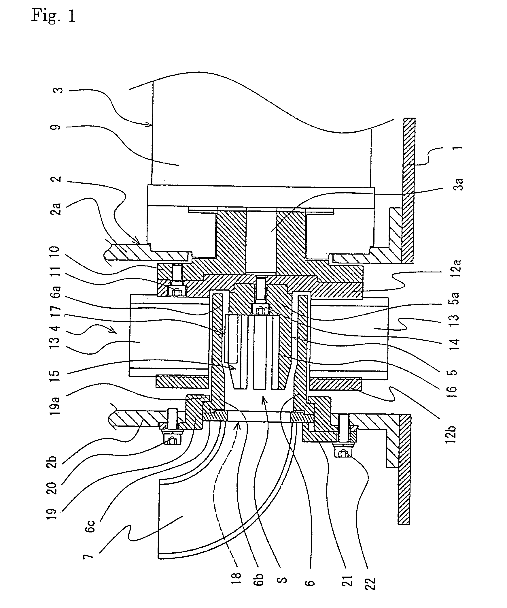
[0028]Now we discuss a control-cage and a centrifugal shot-blasting device using this control-cage, by referring to the drawings. As in FIG. 1, the centrifugal shot-blasting device of the present invention comprises a housing (impeller case) 2, a driving means 3, an impeller 4, a distributor 5, a control-cage 6, and an inlet tube 7. The housing 2 is placed on an upper wall 1 of a polishing chamber for the device. The driving means 3 is placed on the wall 1 and installed outside a lateral side 2a of the housing 2. The impeller 4 is fitted onto the driving shaft 3a of the driving means 3. The distributor 5 is placed in a space S that is inside the impeller 4. The distributor 5 is positioned coaxially with the driving shaft 3a. The control-cage 6 is fixed on the opposite lateral side 2b of the side 2a of the housing 2. The inlet tube is fixed on the side 2b of the housing 2.

[0029]The driving means 3 may be a driving motor that has a bearing (not shown). The bearing rotatably supports t...

example

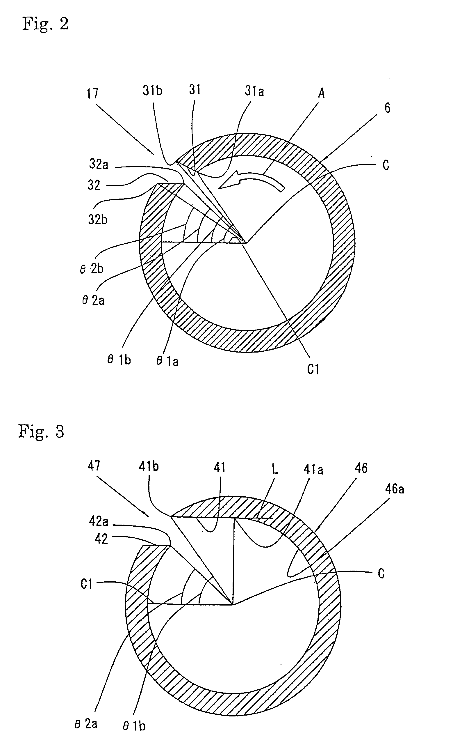
[0040]In this example, as in FIG. 3, a centrifugal shot-blasting device using a control-cage was used. The control-cage has an opening that has an upstream wall 41 and a downstream wall 42. These walls are parallel. Also, the walls are made so that the difference Δθ (=θ1b−θ2a) between the angles θ1b and θ2a is zero. The angle θ1b is measured from the plane C1, containing the central axis C, to the outer edge 41b of the upstream wall 41. The angle θ2a is measured from the plane C1, containing the central axis C, to the inner edge 42a of the downstream wall 42. A test of throwing by this device using SB10 (shot-blasting media made by Sintobrater Co., Ltd.), having an average diameter of 1 mm was carried out, and their distribution (an example) was examined. The result is shown in FIG. 4. The same test of throwing by a device using two conventional types of a control-cage was carried out. One cage had an opening of which the shape of the triangle or the quadrangle is like the Japanese ...

embodiment 2

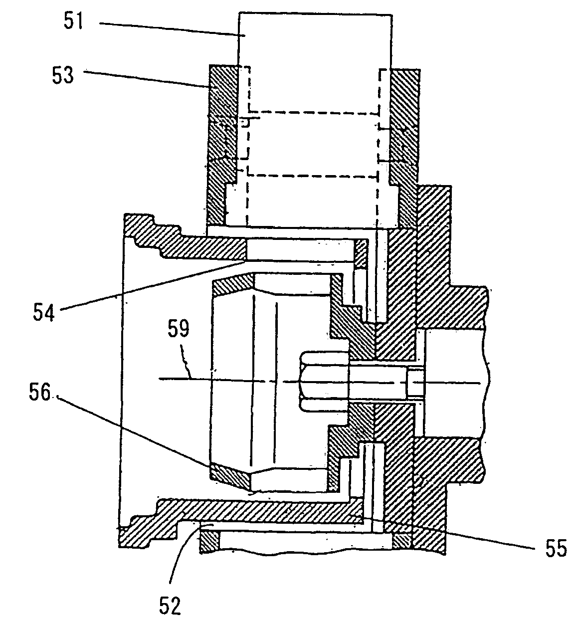
[0043]Now, we discuss an embodiment of the centrifugal shot-blasting device for throwing abrasive grains of the present invention, by referring to FIGS. 6-10. The device comprises an impeller 53, a control-cage 55, and a distributor 56, as in FIG. 8. The impeller 53 is rotatably installed in the device, has a plurality of blades in a radial pattern, and has a cylindrical space 52 in its center. The control-cage 55 is placed in the cylindrical space 52, has a shape of a hollow cylinder, and has an opening 54 for an exit of the abrasive grains, on its lateral side. The distributor 56 is installed in the hollow space of the cage 55 so that it can rotate with the impeller 53.

[0044]The exit of the abrasive grains 54 on the control-cage 55 is approximately an elongated slit that has a given width and that is parallel to the central axis 59 of the control-cage 55, as in FIG. 7. As in FIG. 6, it has an inner wall (upstream wall) 58, which is located opposite (upstream of) the direction of t...


PUM


Abstract

A control-cage that can concentrate the distribution of shot-blasting media, a centrifugal shot-blasting device using this control-cage, and a centrifugal shot-blasting device for throwing abrasive grains, are provided.This control-cage is used for a centrifugal shot-blasting device that rotates an impeller having a plurality of blades at high speed, and that throws shot-blasting media at an object to be processed through the opening of the control-cage by means of the blades. The control-cage is cylindrically shaped and is placed inside the impeller. The opening of the control-cage is made by cutting out the cylindrical part of it in parallel with its central axis. Also, the opening has a quadrangular shape, and has lateral walls located upstream and downstream of the direction of the rotation of the impeller. The upstream wall is made so that the angle between a plane containing the axis and the plane containing both the axis and the inner edge of the upstream wall is larger than the angle between the plane containing the axis and the plane containing both the axis and the outer edge of the upstream wall when they are measured in the direction opposite to the direction of the rotation of the impeller.

Description

FIELD OF INVENTION[0001]The present invention relates to a control-cage, and a centrifugal shot-blasting device and a centrifugal shot-blasting device for throwing abrasive grains, using this control-cage. More particularly, it relates to a control-cage that rotates an impeller having a plurality of blades at high speed, and throws shot-blasting media that are discharged through the opening of the control-cage at an object to be processed, as well relating to a centrifugal shot-blasting device and the device for throwing abrasive grains using this control-cage. The control-cage can concentrate the distribution of shot-blasting media.BACKGROUND OF THE INVENTION[0002]Usually, a shot blasting is carried out so as to flake and remove the rust, burrs, scales, paint, etc., on the surface of an object to be processed by throwing shot-blasting media against it. At the shot blasting, a centrifugal shot-blasting device is used. It rotates an impeller having a plurality of blades at high speed...

Claims


Application Information

Patent Timeline
IPC IPC(8): B24C5/06B24C9/00
CPCB24C5/068
Inventor ITO, MASAKATSUIWATA, KYOICHISUZUKI, HIROAKI
Owner SINTOKOGIO LTD
Why Eureka
Try Eureka