Asymmetrical member for locking ring sectors to a turbine engine casing

a technology of turbine engine and locking ring, which is applied in the direction of machines/engines, liquid fuel engines, lighting and heating apparatus, etc., can solve the problems of not being completely optimised in terms of global achieve the reduction of mass and overall dimensions, satisfactory service life, and the effect of reducing the mean radius and thickness

Active Publication Date: 2009-11-19
SN DETUDE & DE CONSTR DE MOTEURS DAVIATION S N E C M A
View PDF6 Cites 0 Cited by
  • Summary
  • Abstract
  • Description
  • Claims
  • Application Information

AI Technical Summary

Benefits of technology

[0020]In this way, reducing the mean radius and thickness of the first curved joining portion clearly enables the mass and overall dimensions of the locking member of this portion to be minimised, while at the same time being capable of offering a substantially similar criticality in creep to that offered by the second curved joining portion, during operation of the turbine engine. As a matter of fact, since the creep results from the pair of temperature and mechanical stresses, the constant criticality offered by the two joining portions with regard to this creep is explained by the fact that the first portion is more mechanically stressed because of the smaller mean radius and thickness thereof, but less thermally stressed because of the aforesaid temperature gradient.
[0021]Finally, in a general way, it can be stated that the asymmetry employed advantageously allows a reduction in the mass and overall dimensions of the locking member, without it being embrittled from a creep viewpoint, thereby enabling same to have a perfectly satisfactory service life.
[0022]The ratio E1 / E2 is preferably such that 0.3<E1 / E2<1, and the ratio Rm1 / Rm2 is such that 0.3<Rm1 / Rm2<1. Still more preferably, the ratio E1 / E2 is such that 0.5<E1 / E2<0.85, and the ratio Rm1 / Rm2 is such that 0.5<Rm1 / Rm2<0.85. These values are adopted because they make it possible to better adapt to the temperature gradients commonly encountered on turbine engines.

Problems solved by technology

However, a design such as this does not prove to be entirely optimised, in terms of global mass and overall dimensions.

Method used


Image

  • Asymmetrical member for locking ring sectors to a turbine engine casing
  • Asymmetrical member for locking ring sectors to a turbine engine casing
  • Asymmetrical member for locking ring sectors to a turbine engine casing

Examples


Embodiment Construction

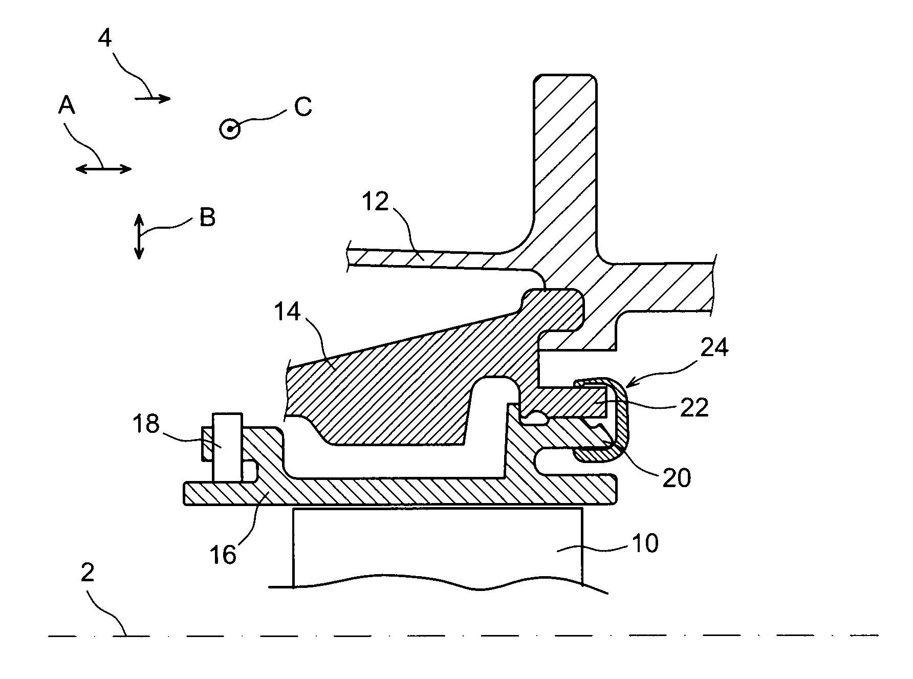
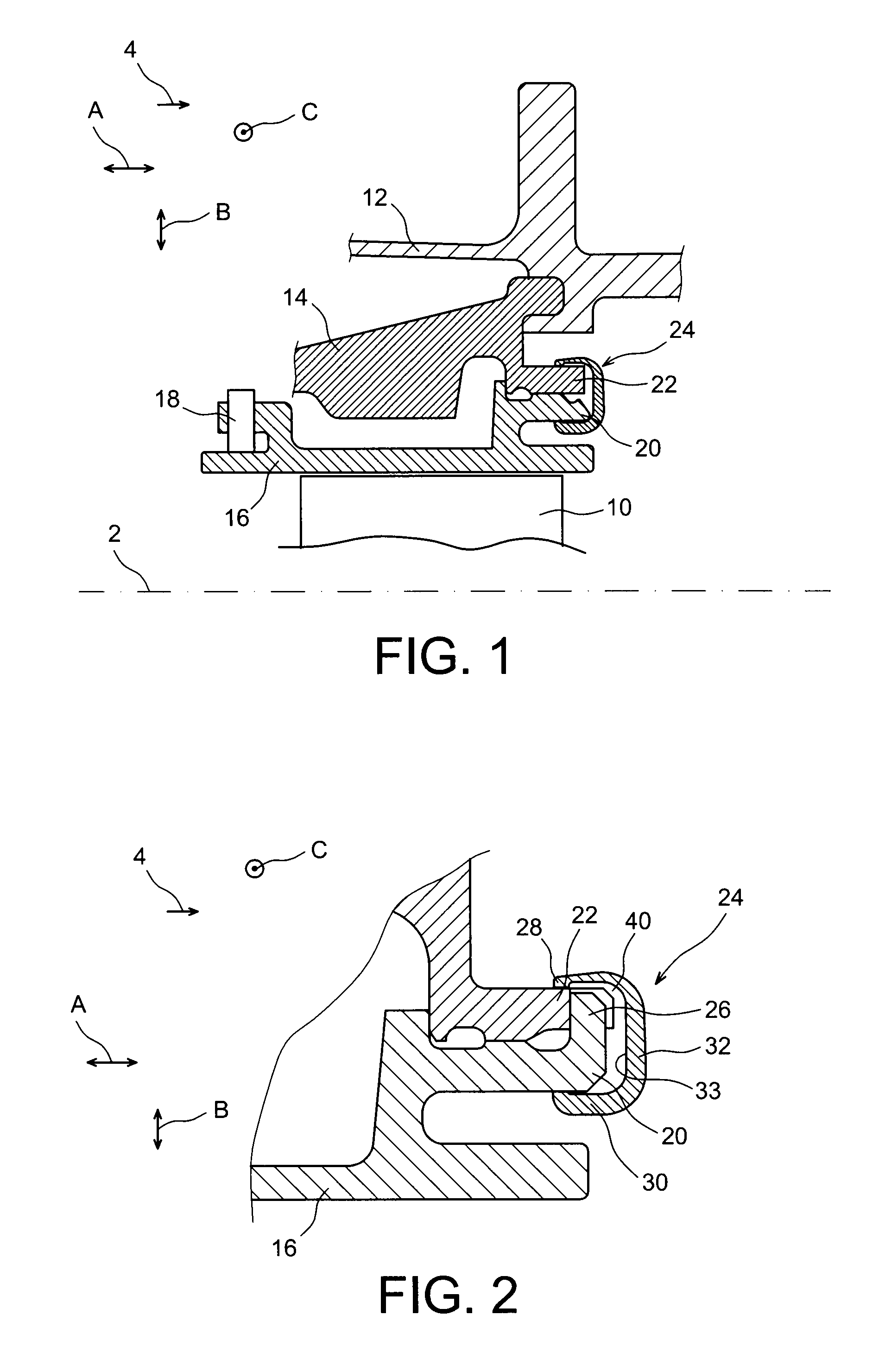
[0039]With joint reference to FIGS. 1 and 2, a device can be seen for fastening ring sectors to an aircraft turbine engine turbine casing, according to a preferred embodiment of this invention.

[0040]In the figures, direction A corresponds to the longitudinal direction or axial direction, which is parallel to the longitudinal axis 2 of the turbine and turbine engine. Direction B corresponds to the radial direction of the turbine, and direction C to the circumferential direction. Furthermore, arrow 4 diagrams the principal direction of gas flow within the turbine engine, which is parallel to direction A, while the terms “front,”“upstream,”“rear,” and “downstream” used in the remainder of the description are to be considered in relation to a direction of forward movement of the aircraft under the influence of the thrust of the turbine engine, this direction of forward movement being opposite to the direction of arrow 4.

[0041]In FIG. 1, reference 10 designates the moving blades of a hig...


PUM


Abstract

This invention relates to a locking member (24) for a device for fastening ring sectors to an aircraft turbine engine casing. The member has first and second clamping branches (28, 30), which are connected together by means of curving joining portions (36a, 36b), via a connecting branch (32), the joining portion (36a) of centre thickness E1 having an inside surface (36a′) of mean radius Rm1, and the joining portion (36b) of centre thickness E2 having an inside surface (36b′) of mean radius Rm2. According to the invention, thickness E1 is strictly smaller than thickness E2, and mean radius Rm1 is strictly smaller than mean radius Rm2.

Description

TECHNICAL FIELD[0001]This invention relates in general to a locking member for a device for fastening ring sectors to an aircraft turbine engine, e.g., a turbine casing.[0002]The invention likewise relates to an aircraft turbine engine comprising such locking members, this turbine engine being capable of assuming the form of a turboprop engine or a turbojet engine.PRIOR ART[0003]It is known from the prior art to fasten ring sectors circumferentially onto the casing, around the moving blades of the turbine of a turbojet engine, these sectors jointly forming a continuous cylindrical casing externally defining the path for stream of gases flowing inside the turbine. The ring sectors are mounted onto an internal casing of the turbine by means of casing elements, which are called intermediate casing elements or spacers, to which they are attached at the front end thereof and held at the rear end thereof by C-shaped or sideways U-shaped locking members. The latter are engaged axially / long...

Claims


Application Information

Patent Timeline
Patent Type & Authority Applications(United States)
IPC IPC(8): F01D25/24
CPCF01D11/24F05D2240/11Y02T50/671F01D25/246Y02T50/60
Inventor ANTUNES, SERGE LOUISDA SILVA, DAVID
Owner SN DETUDE & DE CONSTR DE MOTEURS DAVIATION S N E C M A
Why Eureka
Try Eureka