
Toner container

a technology of toner and container, applied in the field of toner containers, can solve the problems of soiling the inside of the device body, the inability to close the toner may leak from the toner supply port, so as to reduce the amount of toner

Inactive Publication Date: 2009-11-19
MURATA MASCH LTD
View PDF3 Cites 26 Cited by
  • Summary
  • Abstract
  • Description
  • Claims
  • Application Information

AI Technical Summary

Benefits of technology

[0008]In order to overcome the problems described above, preferred embodiments of the present invention provide a toner container that reduces toner leakage at the time of removing the toner container from a toner hopper.
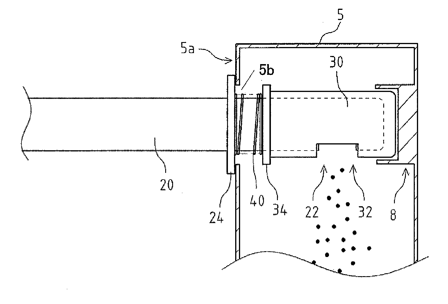
[0013]Since the cover is reciprocated by the cam mechanism between the opening position and the closing position, which is skewed with respect to the opening position, when closing the toner supplying port, the cover moves from the opening position to the closing position while spirally rotating. Thus, the cover can close the toner opening port while scooping up the toner remained around the toner supplying port. As a result, toner leakage that may occur when the toner container is removed from the toner hopper can be reduced.
[0014]The cam mechanism may preferably have a simple shape and configuration. Moreover, by providing two cams, the cover can reliably be reciprocated between the opening position and the closing position.
[0015]After the toner supplying port is closed, the toner supplying port will remain steadily closed due to a biasing force of the elastic body. Therefore, the toner leakage can be reliably prevented even after the toner container is removed from the toner hopper.

Problems solved by technology

When removing the toner container from the toner hopper, the toner may leak from the toner supplying port and soil the inside of a device body.
However, in the above conventional toner container, since the cover moves linearly with respect to the removing portion, the toner supplying port cannot be closed without leaking the toner that remains around the toner supplying port.

Method used


Image

  • Toner container
  • Toner container
  • Toner container

Examples


Embodiment Construction

[0022]Preferred embodiments of the present invention will be described. FIG. 1 is a perspective view illustrating a state in which a developing unit 2, a toner hopper 5, and a toner cartridge 10 of an image forming device according to a preferred embodiment of the present invention are connected with each other. FIG. 2 is a side view illustrating a portion of a supplying pipe 20 in a sectional view. FIG. 3 is a perspective view of portions schematically illustrating an operation of opening and closing a cover 30. FIGS. 4A and 4B are side views of portions schematically illustrating a state in which the toner cartridge 10 is attached to the toner hopper 5. FIGS. 5A and 5B are sectional views illustrating a comparison between the cover of the present preferred embodiment (FIG. 5B) and a cover 130 of a conventional art (FIG. 5A).

[0023]A configuration of the developing unit 2 including the toner cartridge 10 provided as a toner container according to a preferred embodiment of the presen...


PUM


Abstract

A toner cartridge includes a cylindrical supplying pipe having a toner opening port arranged on a side surface thereof; a cylindrical cover that is attached to the supplying pipe and has a cover opening port arranged on a side surface thereof, and a cam mechanism that is provided to the supplying pipe and the cover, and that reciprocates the cover between an opening position where the toner opening port and the cover opening port align with each other and a closing position where the toner opening port is closed by the cover, which closing position is in a skewed position with respect to the opening position. This arrangement provides a toner container that reduces toner leakage when being removed from a toner hopper.

Description

CROSS-REFERENCE TO RELATED APPLICATIONS[0001]This application claims priority under 35 U.S.C. 119 to Japanese Patent Application No. 2008-128759, filed on May 15, 2008, which application is hereby incorporated by reference in its entirety.BACKGROUND OF THE INVENTION[0002]1. Field of the Invention[0003]The present invention relates to a toner container that is removably provided in an image forming device.[0004]2. Description of the Related Art[0005]A conventional facsimile machine, copier, printer, or the like, includes an image forming device, and toner supplied to a developing unit of the image forming device is contained in a toner container. The toner container has a toner supplying port arranged to supply the toner. The toner supplying port is covered by an openable and closable cover. The toner container is removably provided to a toner hopper.[0006]The conventional art discloses, for example, a toner container provided with a cylindrical cover which is attached thereto and re...

Claims


Application Information

Patent Timeline
IPC IPC(8): G03G15/08
CPCG03G2215/0692G03G15/0886G03G15/0877
Inventor NAKAJIMA, TAKEHIRO
Owner MURATA MASCH LTD
Learn More