
Wave transduce having variable energy piston assembly

a variable energy, wave transducer technology, applied in the direction of positive displacement liquid engine, electric generator control, piston pump, etc., can solve the problem that the small wave movement is insufficient to effectively work the piston, and achieve the effect of increasing the buoyancy force acting on the piston and the stroke length, reducing the stroke length, and effective working the piston

Active Publication Date: 2009-11-19
AOE ACCUMULATED OCEAN ENERGY
View PDF4 Cites 7 Cited by
  • Summary
  • Abstract
  • Description
  • Claims
  • Application Information

AI Technical Summary

Benefits of technology

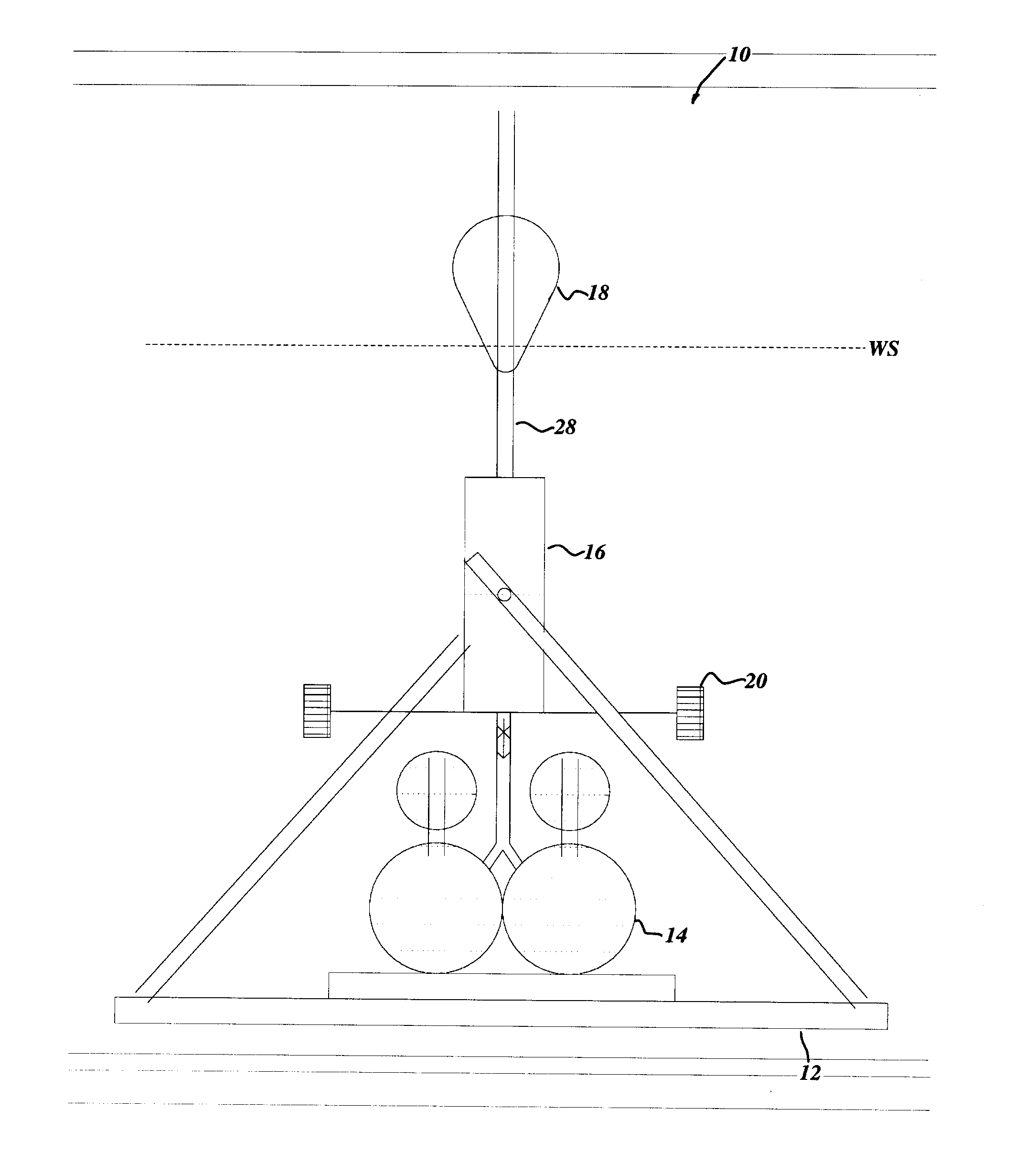
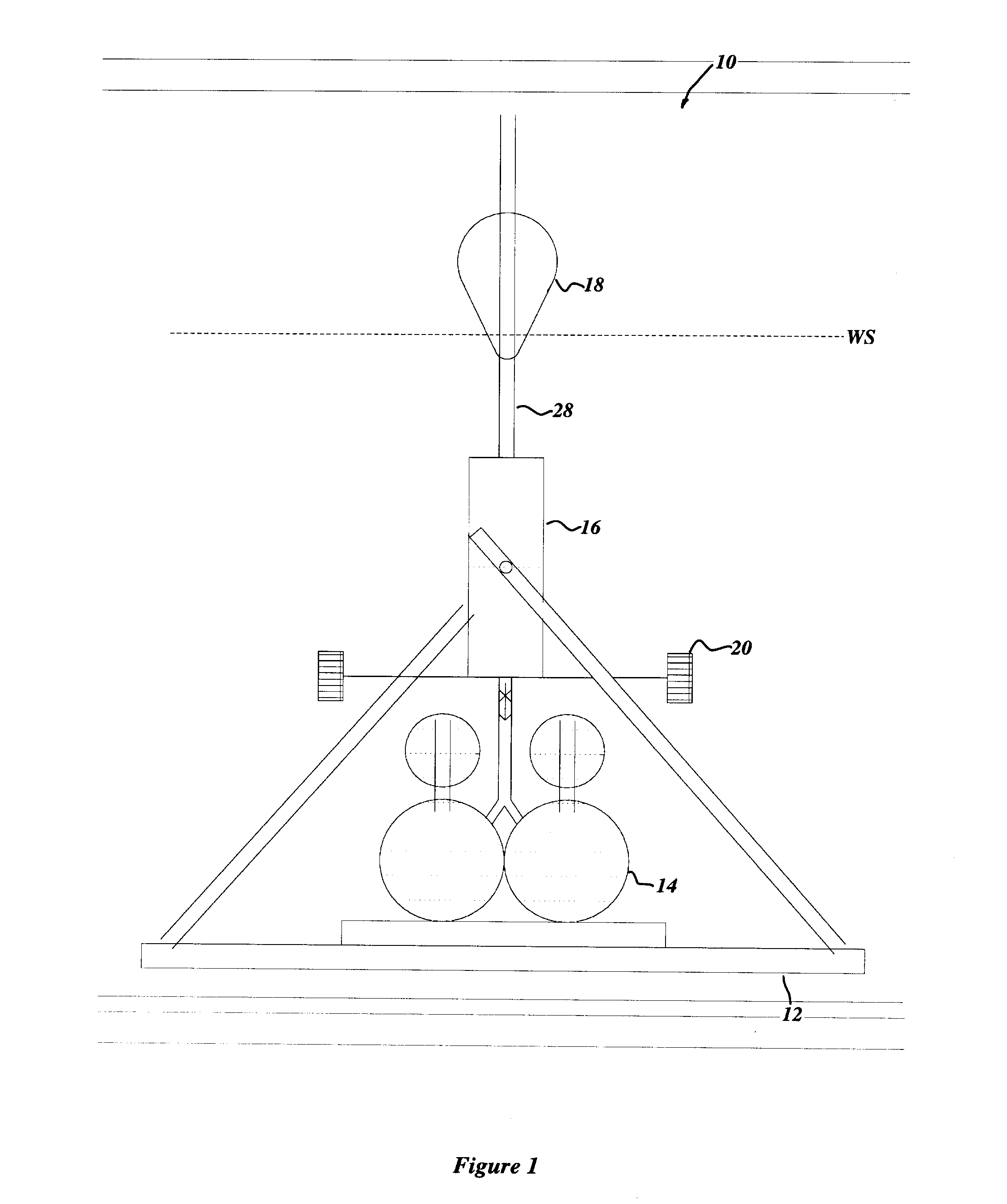
[0008]In general terms, the present invention includes a variable energy piston assembly that accommodates and exploits variable wave amplitudes. As wave amplitude increases, it is possible to increase both the buoyancy forces acting on the piston and the length of the piston's stroke. This adaptation capitalizes on the realization that wave energy increases as the square of wave amplitude. However, as wave amplitudes decrease, it is desirable to decrease the length of stroke, lest the smaller movement of the waves be insufficient to effectively work the piston.
[0025]In another configuration, the low-pressure chamber might jacket the intermediate-pressure chamber instead of abutting one end of it. This configuration could include a low-resistance chamber abutting the low-pressure chamber and the intermediate-pressure chamber, the low-resistance chamber perhaps for example being filled with gas at no greater than the current ambient pressure. In this configuration, at least one of the plurality of cylinders might be housed within the low-resistance chamber, and if that cylinder were telescopic, it would be able to easily expand into the low-resistance chamber by compressing the ambient gas.
[0046]Driving a subset of the pistons could include increasing the aggregate piston-head area of the subset as the extension of the piston rod assembly increases.
[0047]Increasing the aggregate piston-head area of the subset could be accomplished in a number of ways. For example, it could include increasing the number of pistons that are members of the subset as the piston rod assembly extends. As another example, it might include introducing larger-area pistons as members of the subset as the piston rod assembly extends. As still another example, it could include increasing the area of at least one of the pistons that is a member of the subset as the piston rod assembly extends.

Problems solved by technology

However, as wave amplitudes decrease, it is desirable to decrease the length of stroke, lest the smaller movement of the waves be insufficient to effectively work the piston.

Method used


Image

  • Wave transduce having variable energy piston assembly
  • Wave transduce having variable energy piston assembly
  • Wave transduce having variable energy piston assembly

Examples


first embodiment

Energy Accumulator

[0141]FIGS. 3 and 4 show the first embodiment energy accumulator 16a—a multi-piston hydraulic embodiment. Under the urging of the float 18, the variable energy piston assembly 26a operates as follows.

[0142]For calm sea conditions, only the primary cylinder 30a′ will operate, the primary piston-head 32a′ working between the fully charged position and the 1 (a) position.

[0143]As sea conditions become somewhat more energetic and the waves incident on the float 18 have larger amplitudes, the primary piston-head 32a′ travels beyond the 1 (a) position to the 1 (b) position and a first pair of secondary piston-heads 32a″ (pair #2) is engaged by the piston rod assembly 28a and operate between the fully charged position and the 2(b) position.

[0144]The displacement of the float 18 will be such that the pressure desired is achieved in a submergence distance not to exceed (by design and choice), the distance represented by the 1(a) position. A determination of the pressure des...

second embodiment

Energy Accumulator

[0150]FIG. 5 shows the second embodiment energy accumulator 16b—a telescopic hydraulic embodiment. Under the urging of the float 18, the variable energy piston assembly 26b operates as follows.

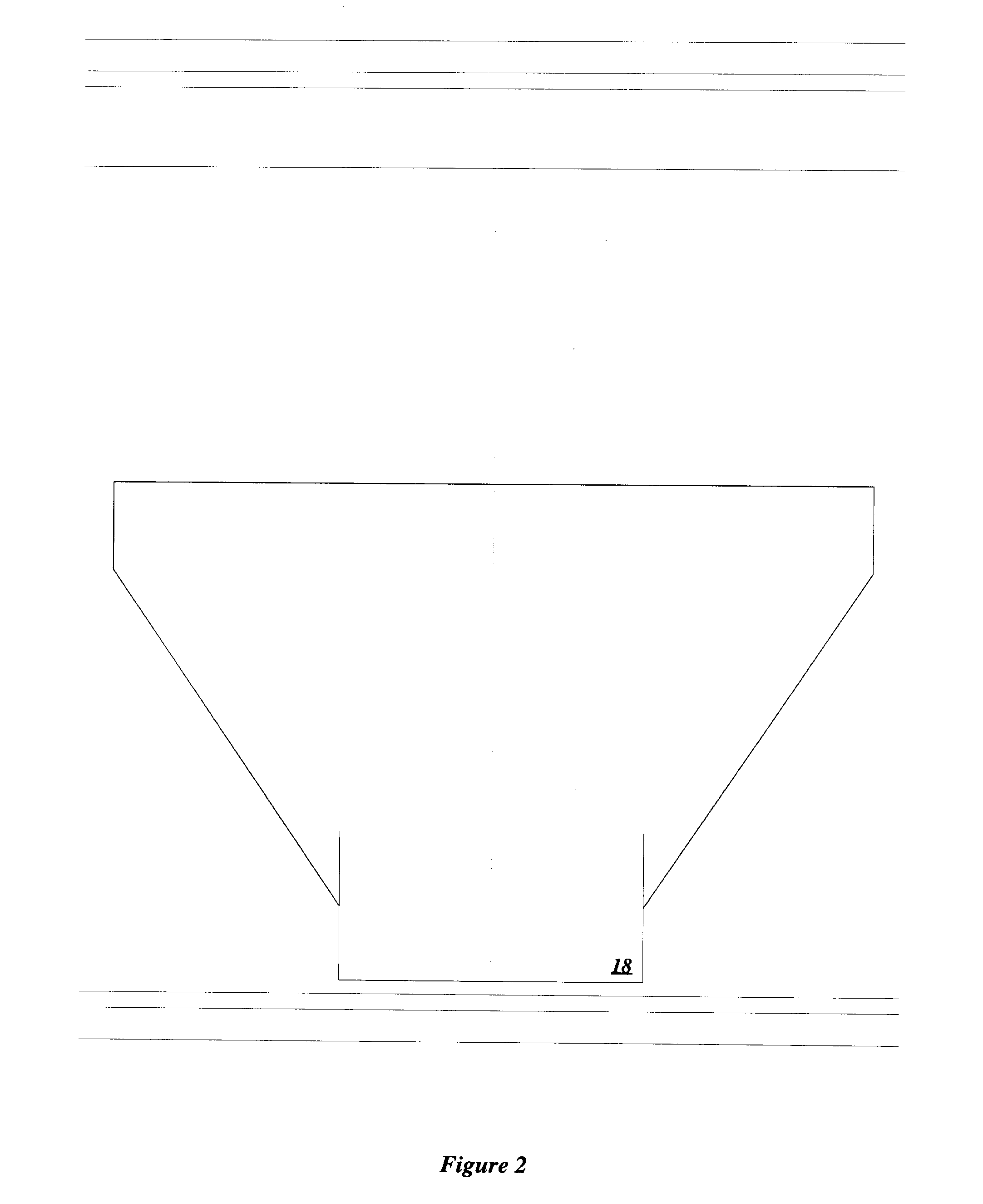
[0151]As the amplitude of waves incident upon the float 18 increases, the float 18 will submerge to an increasing depth and its cross-sectional area at the water surface WS will increase. The float 18 may be configured such that the calculated pressure desired to operate the energy accumulator 16b will be relatively constant.

[0152]The float 18 extends the piston rod assembly 28b as it submerges. For sufficient submergence of the float 18, the piston rod assembly 28b urges the core 32b′ of the telescopic piston-head 32b to traverse the full length of the core cavity 30b′ of the telescopic cylinder 30b.

[0153]Further submergence of the float 18, with the related increased buoyant force, will cause the core 32b′ to travel further, and upon engagement with the medial interior fla...

third embodiment

Energy Accumulator

[0160]FIG. 6 shows the third embodiment of the energy accumulator 16c—an alternate telescopic hydraulic embodiment that operates quite similarly to the second embodiment energy accumulator 16b just described.

[0161]One key difference is that the telescopic cylinder 30c, being housed within the gas-filled low-resistance chamber 42c instead of the liquid filled low-pressure chamber 22b, can expand essentially freely by compressing the ambient gas instead of having to displace a substantially incompressible liquid. This arrangement removes the need for the controlled pressure-relief valve 39b.

[0162]Another key difference is that the low-pressure fluid flows by gravity feed from the low-pressure chamber 22c downward into the telescopic cylinder 30c, providing a more efficient flow.


PUM


Abstract

The present invention relates to a way to adapt a wave transducer to the actual amplitude of incident waves, so as to improve the efficiency of energy conversion. The adaptation includes a variable-energy piston assembly and a tapered float.

Description

CROSS REFERENCE TO RELATED APPLICATIONS[0001]This application claims priority from U.S. Provisional Patent Application Ser. No. 60 / 807,874 filed on Jul. 20, 2006, entitled WAVE TRANSDUCER HAVING VARIABLE ENERGY PISTON, which is expressly incorporated by reference herein.BACKGROUND OF THE INVENTION[0002]1. Field of the Invention[0003]The present invention relates to pistons adapted to convert energy from waves, for example waves in a body of water such as an ocean, lake or river.[0004]2. Description of Related Art[0005]A piston submerged in a body of water may be operated to pressurize a fluid in response to buoyancy forces periodically applied to and removed from a float connected to the distal end of its piston rod by surface waves travelling through the body of water. In this way, some kinetic energy of the incident waves can be converted to potential energy of the pressurized fluid.[0006]However, pistons that have been conventionally adapted for this application suffer from a sig...

Claims


Application Information

Patent Timeline
Patent Type & Authority Applications(United States)
IPC IPC(8): F03C1/02F03B13/24F03B13/18
CPCF03B13/187Y02E10/38F04B35/004F04B17/00Y02E10/30
Inventor SIEBER, JOSEPH D.SIEBER, STEVE A.
Owner AOE ACCUMULATED OCEAN ENERGY
Learn More