
Field coil assembly of electromagnetic clutch for compressor and method for manufacturing the same

a technology of electromagnetic clutch and field coil, which is applied in the direction of mechanical actuated clutches, magnets, magnetic bodies, etc., can solve the problems of deterioration of reliability in the operation of electromagnetic clutch, and easy corrosion between terminals b

Active Publication Date: 2009-11-12
HANON SYST
View PDF17 Cites 15 Cited by
  • Summary
  • Abstract
  • Description
  • Claims
  • Application Information

AI Technical Summary

Benefits of technology

[0022]The present invention is conceived to solve the aforementioned problems in the prior art. An object of the present invention is to provide a field coil assembly having a protective coating portion between a terminal provided at a connector and an end of a wire of a coil connected to the terminal.

Problems solved by technology

However, the prior art discussed above has the following problems.
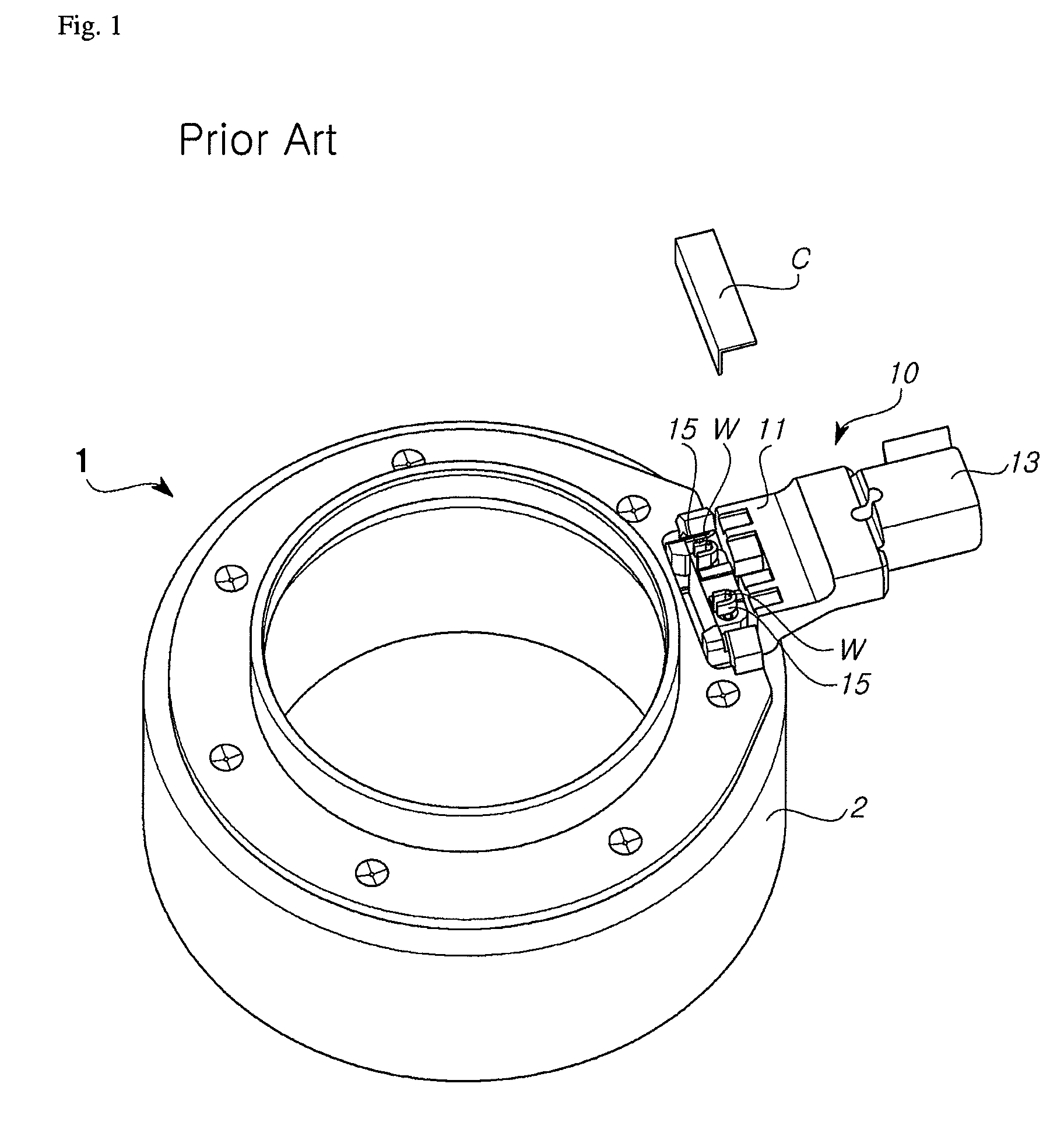
Thus, there is a problem in that galvanic corrosion may easily occur between the terminal 15 and the wire W.
However, the cover C is a separate part, and moisture may penetrate through a gap between the cover C and the connector 10 to thereby cause corrosion between the terminal 15 and the wire W.
Also, this galvanic corrosion may result in electric short circuit between the terminal 15 and the wire W, which deteriorates reliability in operation of the electromagnetic clutch for a compressor.

Method used


Image

  • Field coil assembly of electromagnetic clutch for compressor and method for manufacturing the same
  • Field coil assembly of electromagnetic clutch for compressor and method for manufacturing the same
  • Field coil assembly of electromagnetic clutch for compressor and method for manufacturing the same

Examples


Embodiment Construction

[0037]Hereinafter, preferred embodiments of a field coil assembly of an electromagnetic clutch for a compressor and a method for manufacturing the same according to the present invention will be described in detail with reference to the accompanying drawings.

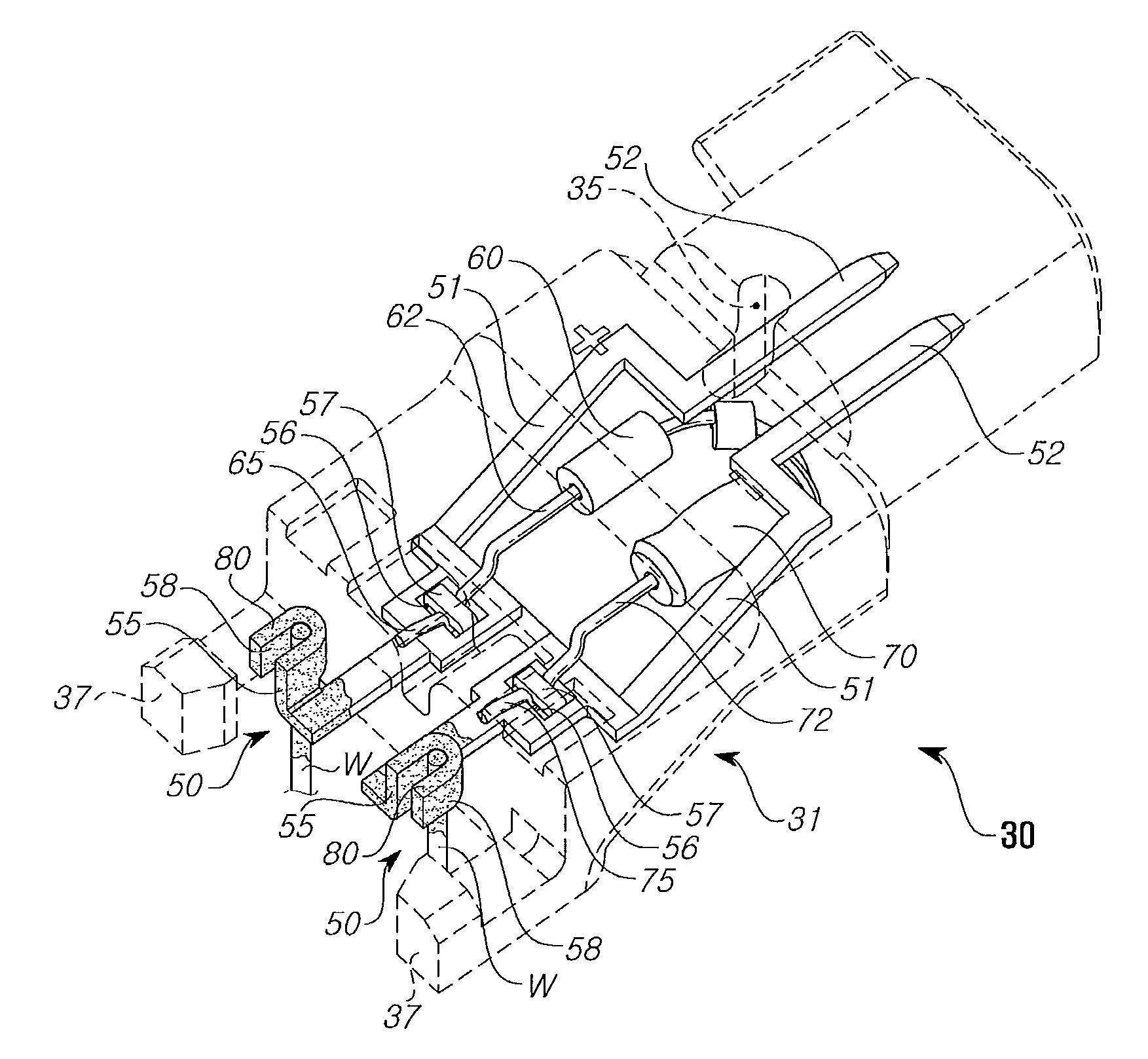
[0038]FIG. 3 is a perspective view showing a preferred embodiment of a field coil assembly of an electromagnetic clutch for a compressor according to the present invention, FIG. 4 is a perspective view showing a connector and a wire of a coil connected thereto employed in the field coil assembly according to the present invention.

[0039]As shown in the figures, a bobbin (not shown) is installed to a core 22 that defines an external appearance and framework of the field coil assembly of an electromagnetic clutch for a compressor, and a coil (not shown) is provided in the bobbin. Also, a fixing cover (not shown) is coupled to the bobbin with the coil interposed therebetween to support the coil.

[0040]The coil is configured by windin...


PUM


Abstract

The present invention relates to a field coil assembly of an electromagnetic clutch for a compressor and a method for manufacturing the same. A field coil assembly 20 of the present invention includes a coil installed to a core 22 and made by winding a wire W to generate a magnetic flux, and a connector 30 coupled thereto. At this time, the connector 30 is provided at one side of the core 22 and has a terminal 50 therein, thereby being electrically connected to one end of the wire W. In addition, a protective coating portion 80 is formed at a connecting portion between the terminal 50 and the end of the wire W to thereby prevent the connecting portion of the wire W and the terminal 50 from being exposed to the outside. According to the present invention, the connecting portion between the terminal 50 and the coil is not exposed to moisture or air, thereby preventing electric short circuit from occurring by galvanic corrosion between the terminal 50 and the coil. As a result, there is an advantage in that the operation reliability and durability of the field coil assembly are improved.

Description

BACKGROUND OF THE INVENTION[0001]1. Field of the Invention[0002]The present invention relates to an electromagnetic clutch for a compressor, and more particularly, to a field coil assembly provided in an electromagnetic clutch for a compressor and a method for manufacturing the same.[0003]2. Description of the Related Art[0004]Generally, an electromagnetic clutch for a compressor is an electric device that forms a magnetic field by electromagnetic induction of a wound coil when power is supplied thereto. The magnetic force formed by the electromagnetic clutch causes a disc of a driving shaft of a compressor to be attracted toward a frictional surface of a pulley and dynamically connected thereto, so that the driving force of the pulley rotated by an engine is transferred to the disc of the driving shaft of the compressor. Accordingly, the electromagnetic clutch manages the power of the compressor according to whether the electric power is applied to the coil, thereby controlling the...

Claims


Application Information

Patent Timeline
IPC IPC(8): H01F7/128
CPCF16D27/14H01F2007/062H01F7/128F16D27/112F16D27/10
Inventor OH, SUNG-TAEGPARK, TAE-YOUNG
Owner HANON SYST
Learn More