Eureka AIR delivers breakthrough ideas for toughest innovation challenges, trusted by R&D personnel around the world.

Semiconductor device and manufacturing method thereof

a technology of semiconductors and manufacturing methods, applied in semiconductor devices, basic electric elements, electrical apparatus, etc., can solve the problems of reducing the effective channel, increasing the difficulty of obtaining junctions, undesirable integration problems, etc., and preventing waste of process time and cost for removing un-reacted pt-containing metal layers. , the effect of reducing the narrow line width

Inactive Publication Date: 2009-11-12
UNITED MICROELECTRONICS CORP
View PDF12 Cites 43 Cited by
  • Summary
  • Abstract
  • Description
  • Claims
  • Application Information

AI Technical Summary

Benefits of technology

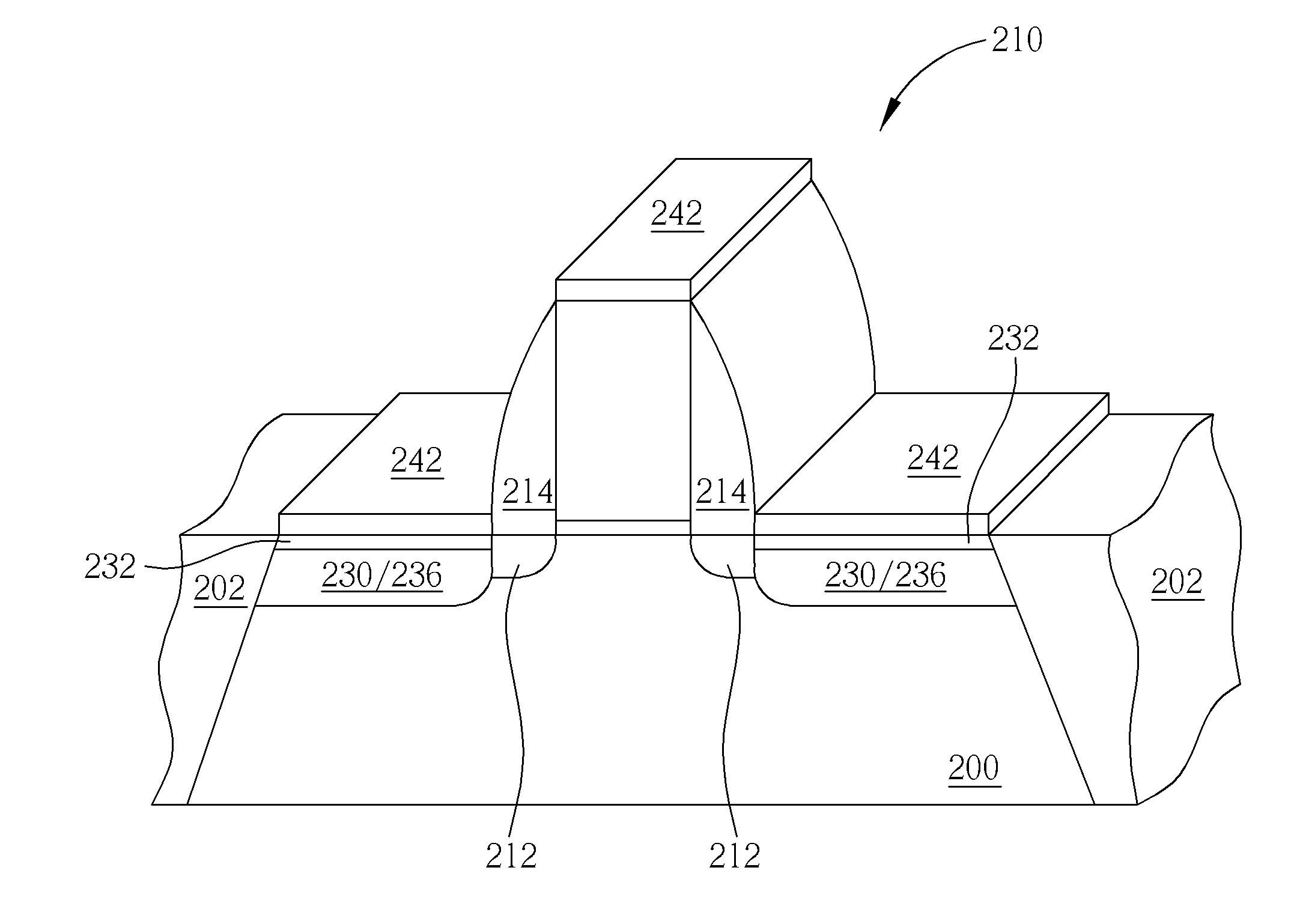
[0008]It is therefore a primary objective of the claimed invention to provide a semiconductor device and manufacturing method thereof that are capable of simultaneously reducing SCE and TED effect.
[0012]According to the present invention, PAI is replaced with the deposition process for forming the top amorphous layer / barrier layer. Thus TED effect is eliminated while SCE is still reduced by the top amorphous layer / barrier layer formed by the deposition process. Furthermore, the narrow line width effect is reduced by the top amorphous layer, which serves as the barrier layer. Therefore application of Pt in salicide process is eliminated, and thus waste of process time and cost for removing un-reacted Pt-containing metal layer is prevented by the provided method.

Problems solved by technology

However, downsizing of the devices results in reduced effective channel regions that causes a well-known undesirable effect: short channel effect (SCE).
Nevertheless, it is getting more and more difficult to obtain junctions that satisfy certain requirement by performing conventional ion implantation and rapid thermal annealing (RTA) as the devices are scaled down.
For example, pre-amorphization implantation (PAI) is introduced to form an amorphous layer for controlling junction depth precisely and lowering laser beam energy, which may cause undesirable integration problems.
However, it is observed that considerable interstitial defects are created by PAI because the implanting ion causes damage to the silicon lattice of the substrate.
TED effect not only deepens the junction profile, but also makes the distribution of the dopant not sheer in a lateral direction, and ironically resulting in severe SCE.
Accordingly, it has become a dilemmatic problem in the conventional method for manufacturing a semiconductor device: in order to reduce SCE and narrow line width effect, PAI is introduced; but PAI itself causes significant TED effect that results in severe SCE and adversely affects reliability of the devices.

Method used


Image

  • Semiconductor device and manufacturing method thereof
  • Semiconductor device and manufacturing method thereof
  • Semiconductor device and manufacturing method thereof

Examples


Embodiment Construction

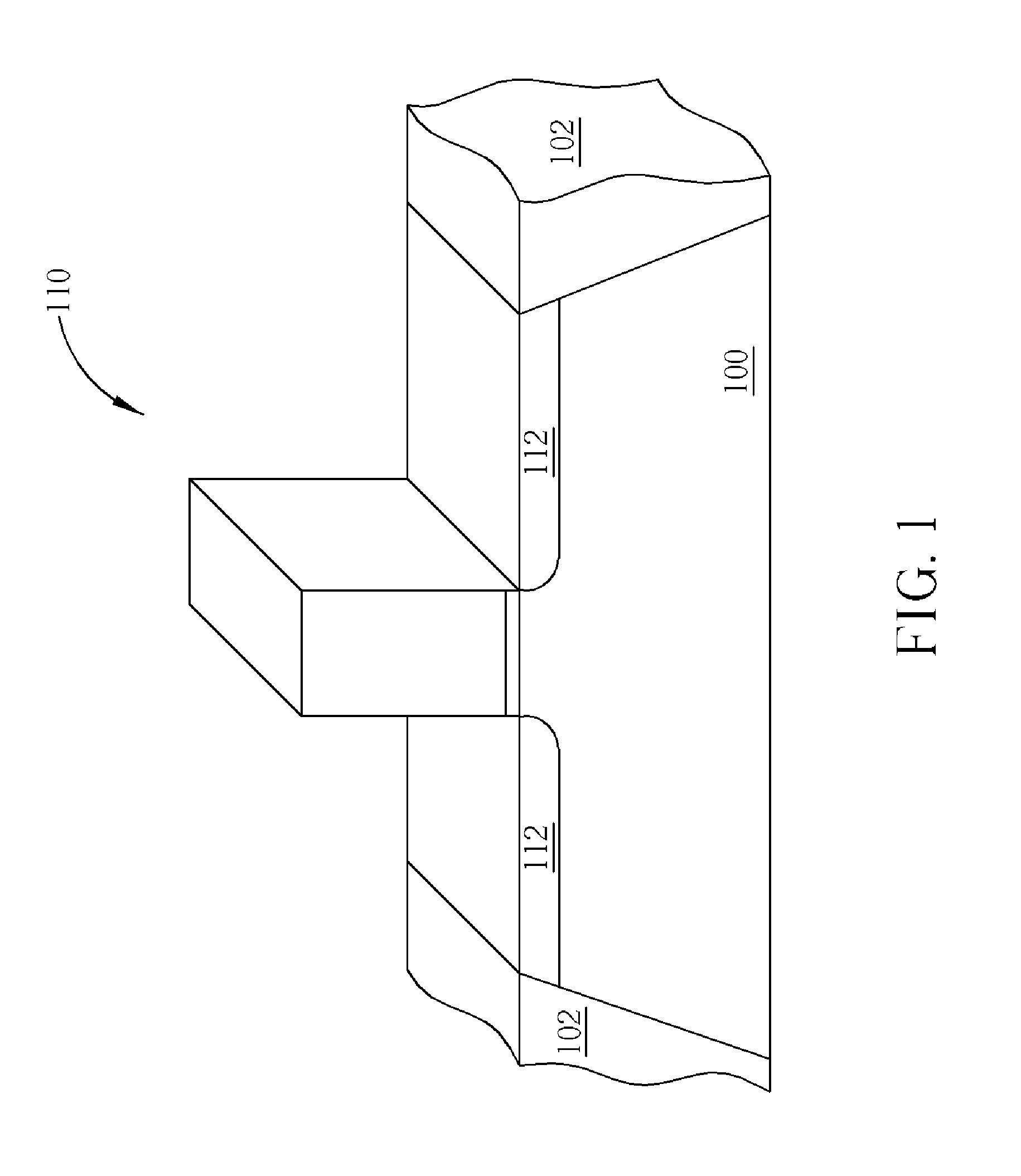
[0016]Please refer to FIGS. 1-5, which are schematic drawings illustrating a first preferred embodiment of the method for manufacturing a semiconductor device provided by the present invention. As shown in FIG. 1, a substrate 100 having at least a gate structure 110 formed thereon is provided firstly. The substrate 100 also comprises shallow trench isolations (STIs) 102 used to provide electrical isolations between devices. Then, as shown in FIG. 1, lightly doped drains (LDDs) 112 are formed in the substrate 100 respectively at two sides of the gate structure 110.

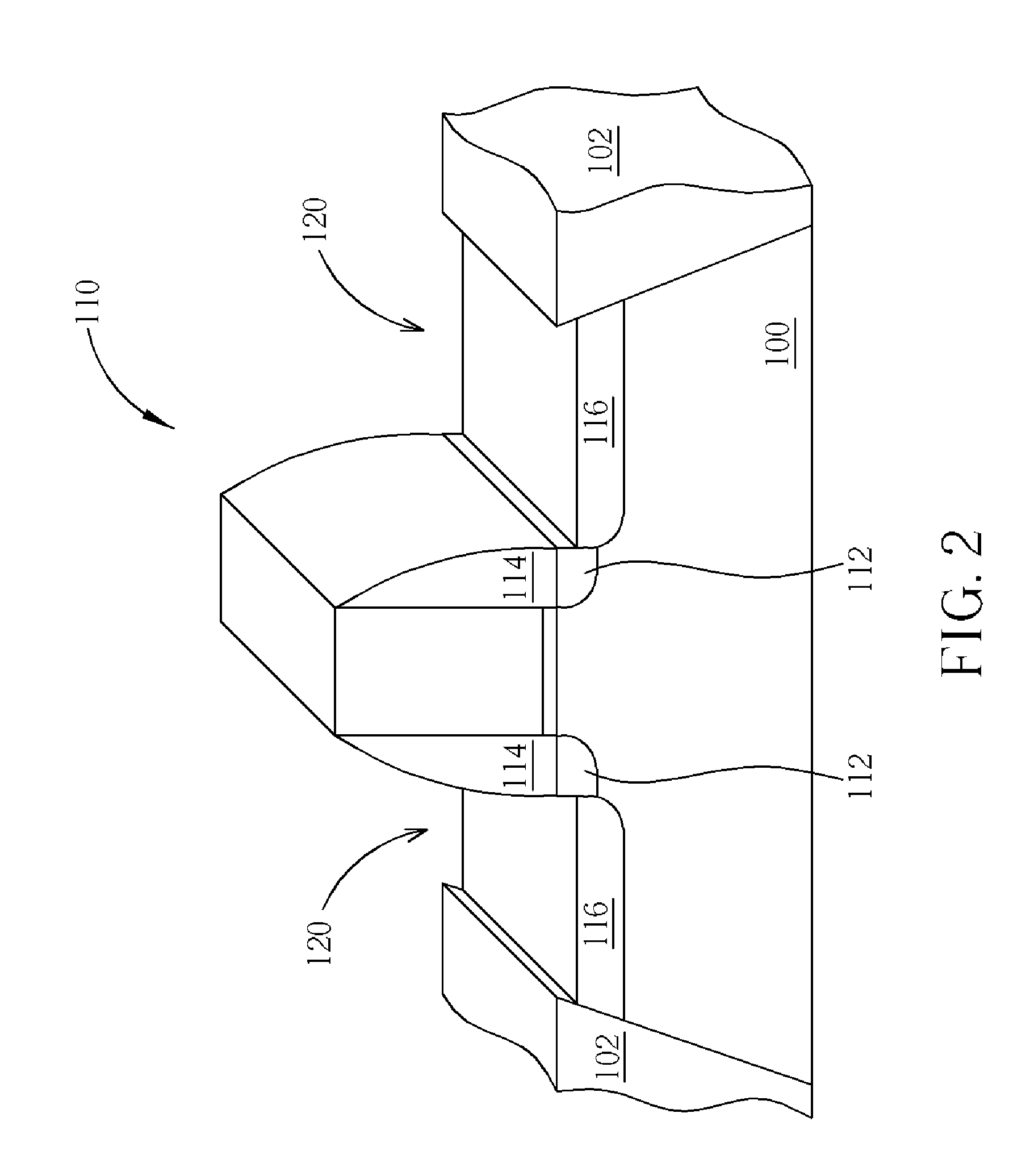
[0017]Please refer to FIG. 2. Next, a spacer 114 is formed at sidewalls of the gate structure 110 and followed by forming a source / drain 116 in the substrate 100 at two sides of the gate structure 110. After forming the source / drain 116, an etching process is performed to form recesses 120 respectively in the source / drain 116. In the first preferred embodiment, a depth of the recess 120 is substantially between 100 and 200 ...


PUM


Abstract

A method for manufacturing a semiconductor device includes providing a substrate having at least a gate structure formed thereon, forming LDDs in the substrate respectively at two side of the gate structure and a spacer at sidewalls of the gate structure, forming a source / drain in the substrate at two side of the gate structure, performing ant etching process to form recesses respectively in the source / drain, forming a barrier layer in the recesses; and performing a salicide process.

Description

BACKGROUND OF THE INVENTION[0001]1. Field of the Invention[0002]The present invention relates to a semiconductor device and manufacturing method thereof, and more particularly, to a semiconductor device and manufacturing method capable of replacing pre-amorphous implantation (PAI).[0003]2. Description of the Prior Art[0004]In accordance with the recent trend toward small-sized, lightweight, and slim electronic devices, semiconductor devices are scaled to smaller and smaller dimensions. However, downsizing of the devices results in reduced effective channel regions that causes a well-known undesirable effect: short channel effect (SCE). To suppress SCE, shallower and sharper junctions are needed in transistors. Nevertheless, it is getting more and more difficult to obtain junctions that satisfy certain requirement by performing conventional ion implantation and rapid thermal annealing (RTA) as the devices are scaled down.[0005]Therefore various methodologies are proposed to obtain sh...

Claims


Application Information

Patent Timeline
Patent Type & Authority Applications(United States)
IPC IPC(8): H01L29/778H01L21/336
CPCH01L21/28518H01L21/3148H01L29/66636H01L29/665H01L29/456H01L21/02167
Inventor YANG, YUN-CHICHIANG, JIH-SHUNLIN, CHENG-LICHEN, JU-PINGSU, KUAN-CHENG
Owner UNITED MICROELECTRONICS CORP
Why Eureka
Eureka Blog
Learn More