
Pad spring of disc brake and method for manufacturing the same

a technology of disc brakes and pads, which is applied in the field of pads of disc brakes, can solve the problems of difficult smooth sliding motion of the pad plate, poor lubricating performance of grease, and loud nois

Inactive Publication Date: 2009-11-12
KIM DOE HEE
View PDF11 Cites 36 Cited by
  • Summary
  • Abstract
  • Description
  • Claims
  • Application Information

AI Technical Summary

Benefits of technology

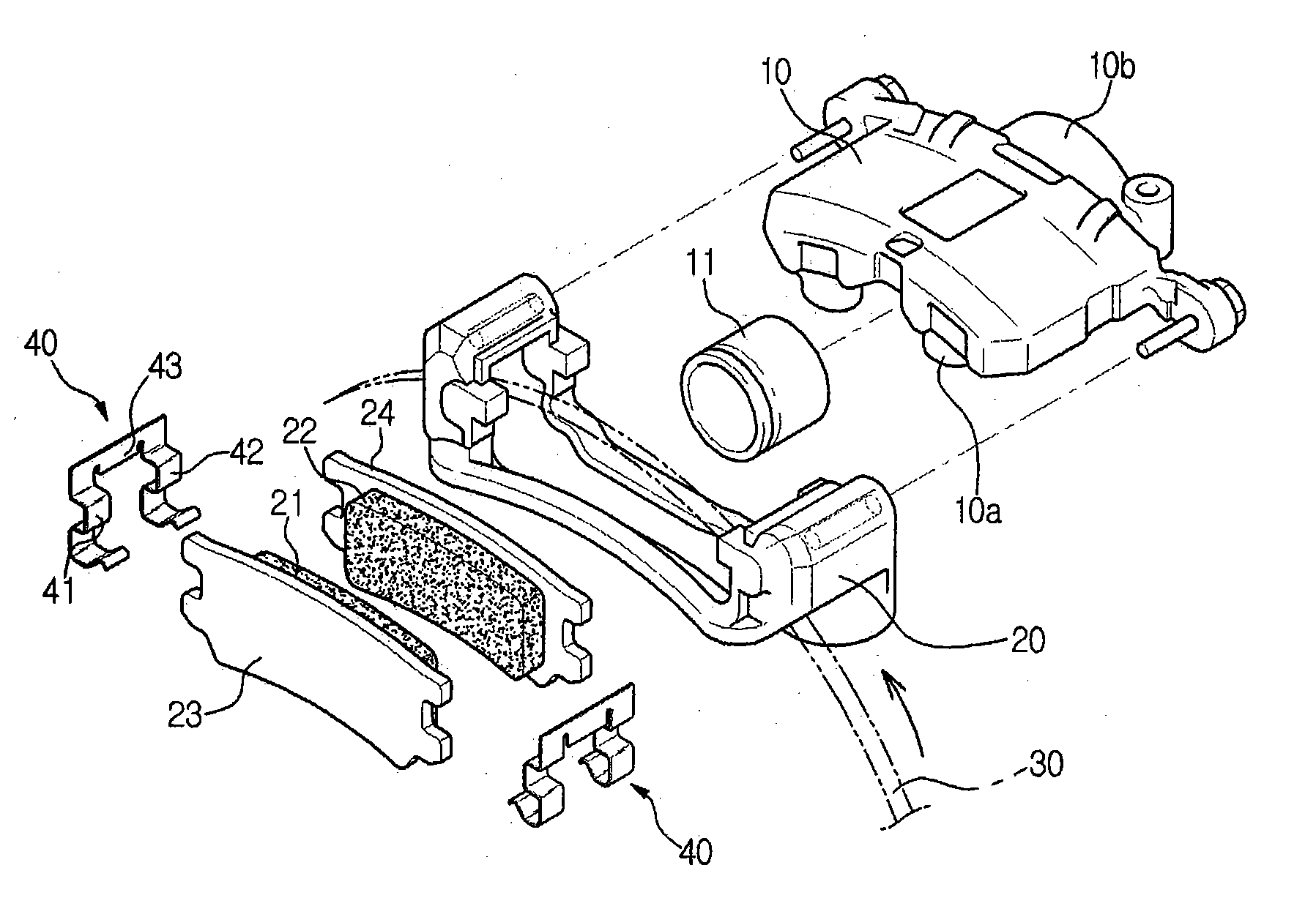
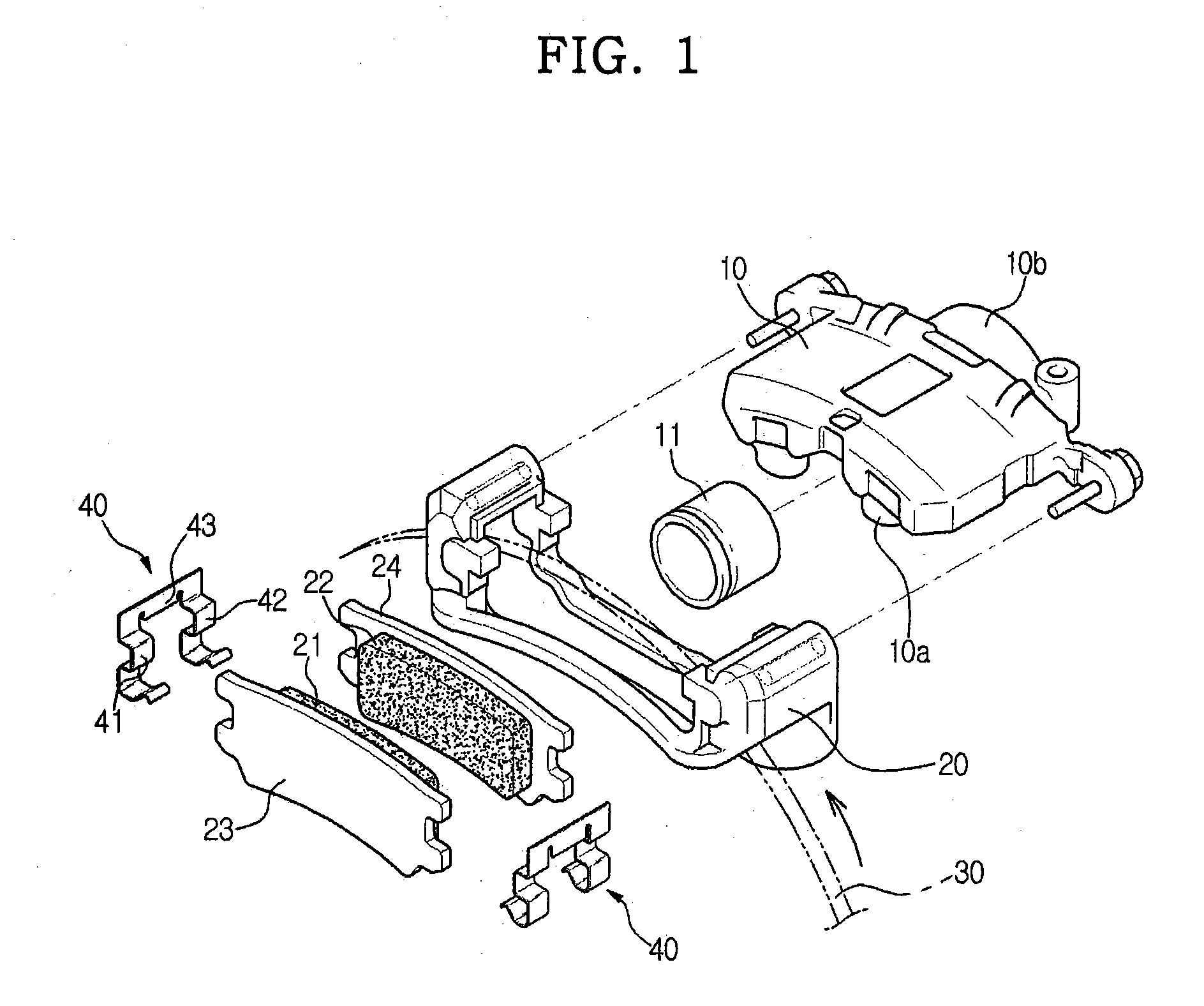
[0012]Therefore, one aspect of the invention is to provide a pad spring of a disc brake, which guides the sliding motion of pad plates and reduces vibration transmitted from the pad plates to a carrier concurrently, and continuously maintains these functions for a long time, and a method for manufacturing the same.
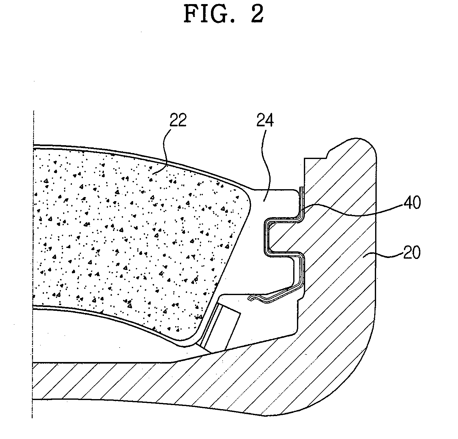
[0013]In accordance with one aspect, the present invention provides a pad spring of a disc brake, in which a pair of pad plates sliding towards a disc is accommodated in a carrier fixed to a vehicle frame such that friction pads are respectively attached to the facing inner surfaces of the pad plates so as to press both surfaces of the disc rotated together with the rotation of a wheel and thus fix the disc, and pad springs for guiding the sliding motion of the pad plates and preventing vibration applied to the pad plates from being transmitted to the carrier are interposed among the pad plates and the carrier, wherein one surface of the pad spring contacting the pad plates is coated with a low frictional material and the other surface of the pad spring contacting the carrier is coated with an elastic material.
[0019]In accordance with another aspect, the present invention provides a method for manufacturing a pad spring of a disc brake comprising sanding or corroding both surfaces of a metal plate for forming the pad spring; coating one surface of the sanded or corroded metal plate with a low frictional material and the other surface of the sanded or corroded metal plate with an elastic material; processing the metal plate, coated with the low frictional material and the elastic material, by pressing and bending so as to form a shape of the pad spring; and removing stress, applied to bending regions of the pad spring during the processing of the metal plate, by heat treatment.
[0020]In accordance with yet another aspect, the present invention provides a method for manufacturing a pad spring of a disc brake comprising processing a metal plate by pressing and bending so as to form a shape of the pad spring; sanding or corroding both surfaces of the pad spring; coating one surface of the sanded or corroded pad spring with a low frictional material and the other surface of the sanded or corroded pad spring with an elastic material; and removing stress, applied to bending regions of the pad spring during the processing of the metal plate, by heat treatment.

Problems solved by technology

The conventional disc brake generate problems, such as loud noise or a difficulty of a smooth sliding motion of the pad plates due to friction caused by direct contact between the pad plates and the pad springs, respectively made of metals, when the pad plates slide so as to press the disc.
However, as time passes, grease tends to gel and thus a designated amount of grease must be frequently added.
Further, in the case that abrasion dust generated by the friction between the disc and the friction pads sticks to the friction planes coated with grease, grease cannot exhibit original lubricating performance.

Method used


Image

  • Pad spring of disc brake and method for manufacturing the same
  • Pad spring of disc brake and method for manufacturing the same
  • Pad spring of disc brake and method for manufacturing the same

Examples


first embodiment

[0039]In accordance with a first embodiment, as shown in FIG. 4, the pad spring 40 of the present invention is manufactured through a coating preparing step (100), a coating step (200), a shape forming step (300), and a stress removal heat treating step (400), which are sequentially carried out.

[0040]In the coating preparing step (100), both surfaces of a metal plate made of stainless steel or spring steel for forming the pad spring 40 are sanded or corroded such that both the surfaces of the metal plate can be effectively coated with the low frictional material 50 and the elastic material 60. In the coating step (200), both the surfaces of the sanded or corroded metal plate are coated with the low frictional material 50 and the elastic material 60.

[0041]Here, Teflon is employed as the low frictional material 50 and heat resistant reinforced rubber and Urethane are employed as the elastic material 60 so as to be able to stand heat of a high temperature in the stress removal heat tre...

second embodiment

[0045]Further, in accordance with a second embodiment, as shown in FIG. 5, the pad spring 40 of the present invention is manufactured through a shape forming step (500), a coating preparing step (600), a coating step (700), and a stress removal heat treating step (800), which are sequentially carried out.

[0046]In the shape forming step (500), a metal plate made of stainless steel or spring steel has a shape of a pad spring 40 through pressing and bending processes. In the coating preparing step (600), both surfaces of the pad spring 40 are sanded or corroded such that both the surfaces of the pad spring 40 can be effectively coated with the low frictional material 50 and the elastic material 60. In the coating step (700), both the surfaces of the sanded or corroded pad spring 40 are coated with the low frictional material 50 and the elastic material 60.

[0047]Here, Teflon is employed as the low frictional material 50 and heat resistant reinforced rubber and Urethane are employed as t...


PUM

PropertyMeasurementUnit
thicknessaaaaaaaaaa
thicknessaaaaaaaaaa
thicknessesaaaaaaaaaa

Abstract

Disclosed are a pad spring of a disc brake, which guides the sliding motion of pad plates and reduces vibration transmitted from the pad plates to a carrier concurrently, and continuously maintains these functions for a long time, and a method for manufacturing the same. In a pad spring of a disc brake, in which a pair of pad plates sliding towards a disc is accommodated in a carrier fixed to a vehicle frame such that friction pads are respectively attached to the facing inner surfaces of the pad plates so as to press both surfaces of the disc rotated together with the rotation of a wheel and thus fix the disc, and pad springs for guiding the sliding motion of the pad plates and preventing vibration applied to the pad plates from being transmitted to the carrier are interposed among the pad plates and the carrier, one surface of the pad spring contacting the pad plates is coated with a low frictional material and the other surface of the pad spring contacting the carrier is coated with an elastic material.

Description

BACKGROUND OF THE INVENTION[0001]1. Field of the Invention[0002]The present invention relates to a disc brake, and more particularly, to a pad spring of a disc brake, which guides the sliding motion of pad plates and reduces vibration applied to the pad plates, and a method for manufacturing the same.[0003]2. Description of the Related Art[0004]In general, disc brakes are apparatuses, which forcibly attach friction pads respectively to both side surfaces of a disc, rotating together with the rotation of a wheel of a vehicle, and thus brake and decelerate the vehicle through the frictional force.[0005]Such a disc brake includes a caliper housing having a piston, advancing and retreating by hydraulic brake pressure, therein, a carrier fixed to a vehicle frame and having a pair of pad plates such that friction pads are respectively attached to the facing inner surfaces of the pad plates, and a disc, a portion of the outer circumferential surface of which is inserted into a gap between ...

Claims


Application Information

Patent Timeline
Patent Type & Authority Applications(United States)
IPC IPC(8): F16D65/40B23P17/00
CPCF16D65/0972Y10T29/49982F16D2250/0046F16D65/0977
Inventor KIM, DOE HEE
Owner KIM DOE HEE
Learn More