
Laser ablation apparatus and method

a laser ablation and apparatus technology, applied in the direction of optical radiation measurement, separation process, instruments, etc., can solve the problems of inability to match known standards achieved with other analysis methods, unreliable and inaccurate libs type spectrometry, and method inherent problems

Active Publication Date: 2009-11-05
APPLIED SPECTRA
View PDF12 Cites 89 Cited by
  • Summary
  • Abstract
  • Description
  • Claims
  • Application Information

AI Technical Summary

Benefits of technology

[0007]In accordance with a second aspect of the present invention, a method of laser ablation spectroscopy is provided. The method includes a protocol of generating one or more laser ablations to a sample site. The spectral data of the total number of laser ablations for the sites are averaged together. In one embodiment, the total number of laser ablations for the sample site equals three laser ablations. The protocol includes laser ablating additional sample sites and averaging the spectral data of the total number of sample sites. In one embodiment, the total number of sample sites equals twenty sample sites.

Problems solved by technology

This method has inherent disadvantages.
The LIBS type of spectrometry has been an unreliable and inexact measurement system since there is a large variation in the recorded data.
Former LIBS type analysis was unsuccessful in matching known standards achieved with other analysis methods.

Method used


Image

  • Laser ablation apparatus and method
  • Laser ablation apparatus and method
  • Laser ablation apparatus and method

Examples


Embodiment Construction

[0018]In the following description, numerous details and alternatives are set forth for the purpose of explanation. However, one of ordinary skill in the art will realize that the invention can be practiced without the use of these specific details. In other instances, well-known structures and devices are shown in block diagram form in order not to obscure the description of the invention with unnecessary detail.

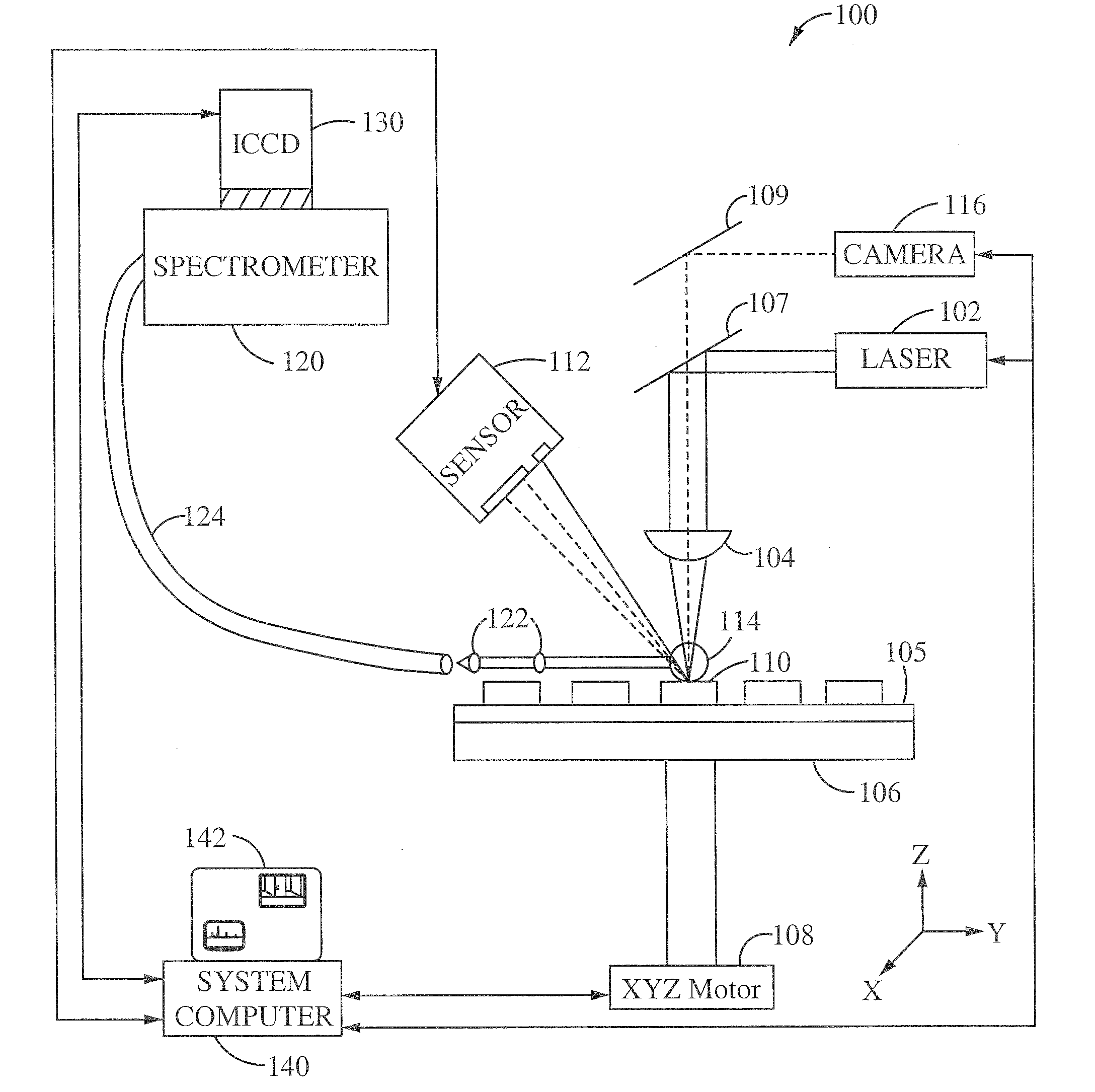
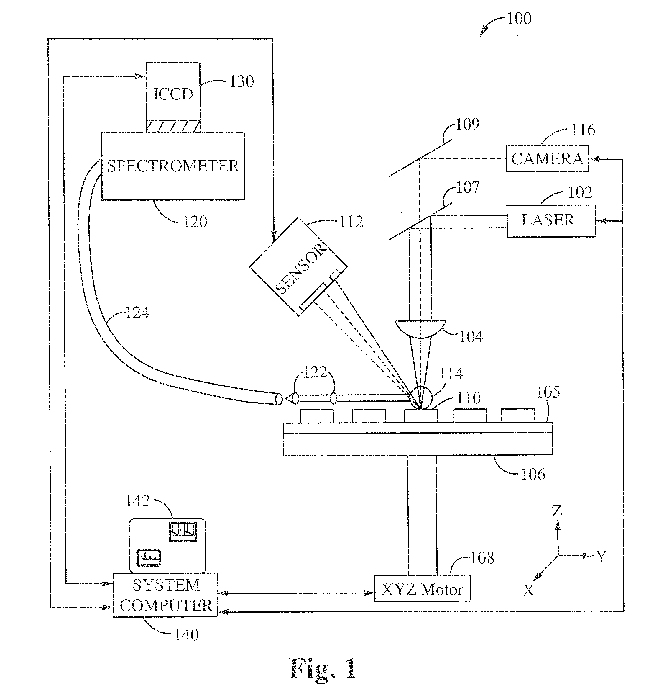
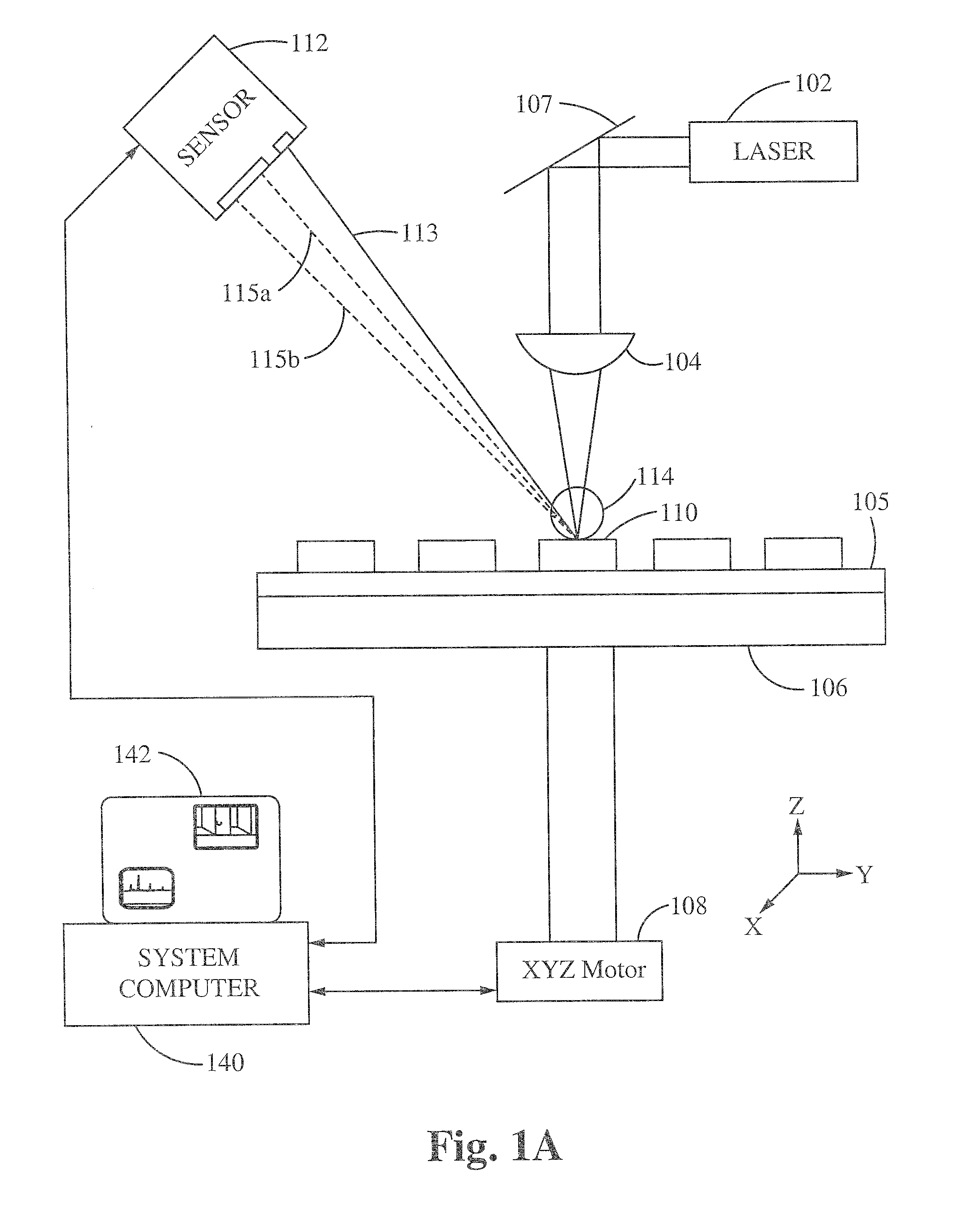
[0019]FIG. 1 shows a schematic overview of a laser ablation apparatus 100 according to the present invention. The apparatus 100 generally includes a pulse laser 102, a stage 106, a position sensor 112, a spectrometer 120 and a system computer 140. The apparatus 100 is configured to generate laser pulses from the pulse laser 102. The laser pulses are focused onto a sample 105 with a lens 104 to produce a plasma plume 114 of the sample 105 at a sample site 110. The position sensor 112 is electrically coupled with the system computer 140 for sending a displacement error signal...


PUM

PropertyMeasurementUnit
wavelengthaaaaaaaaaa
sizeaaaaaaaaaa
spot sizeaaaaaaaaaa

Abstract

Provided is a laser ablation spectroscopy apparatus and method. A pulse laser is focused on the sample site to generate a plasma plume during a laser ablation process. The plasma plume is detected with a spectrometer and an intensified charge coupled device. A sample of material is coupled to a stage movable in the x, y and z directions using an array of x-y-z motors. A change in the height of the sample is detected using a triangulation sensor. The apparatus includes a system computer for synchronizing the movement of the stage in the x, y and z direction during the laser ablation process. The method includes a protocol of generating one or more laser ablations per sample site. The spectral data of the total number of laser ablations for each sample site are averaged together. The protocol includes laser ablating additional sample sites and averaging the spectral data of the total number of sample sites.

Description

[0001]This patent application claims priority under 35 U.S.C. 119 (e) of the co-pending U.S. Provisional Patent Application Ser. No. 61 / 126,633, filed May 5, 2008, and entitled “LASER ABLATION APPARATUS AND METHOD”. The Provisional Patent Application Ser. No. 61 / 126,633 filed May 5, 2008, and entitled “LASER ABLATION APPARATUS AND METHOD” is also hereby incorporated by reference.BACKGROUNDField of the Invention[0002]Restriction of hazardous substances by statutes such as the Directive on the Restriction of the Use of Certain Hazardous Substances in Electrical and Electronic Equipment 2002 / 95 / EC (commonly referred to as the Restriction of Hazardous Substances Directive or RoHS) was adopted in February 2003 by the European Union. The state of California has passed a similar law. The directive restricts the use of six hazardous materials in the manufacture of various types of electronic and electrical equipment. The six hazardous materials include Lead, Mercury, Cadmium, Hexavalent chr...

Claims


Application Information

Patent Timeline
Patent Type & Authority Applications(United States)
IPC IPC(8): G01J3/30H01J49/00
CPCB23K26/03B23K26/048H01J49/0463G01J3/443G01N21/718B23K26/0861
Inventor YOO, JONG HYUNTRIBE, RANDOLPH S.LIU, CHUNYI
Owner APPLIED SPECTRA
Learn More