
Illumination device

Inactive Publication Date: 2009-10-29
MABUCHI TOSHIHIKO
View PDF15 Cites 8 Cited by
  • Summary
  • Abstract
  • Description
  • Claims
  • Application Information

AI Technical Summary

Benefits of technology

[0049]In the illumination device according to the present invention, the number of times of the energy conversion for supplying visible rays is only once, which means a small loss by the energy conversion. Further, high-temperature heat rays with high energy are collected as electricity by thermoelectric conversion when necessary, and when the device is combined with an exhaust gas heat exchanger, uncollected heat can be collected as hot water or steam, which enables cascade use of energy and thus is efficient.
[0050]Further, not having a moving part which rotates or reciprocates, the illumination device is far quieter than an internal combustion engine, turbine or the like. Further, since light supplied from the illumination device according to the present invention is light which is obtained after light in the heat ray spectrum is filtered out, this light gives smaller influence of increasing indoor cooling air-conditioning load than conventional illumination such as a fluorescent light and an incandescent light.
[0051]The high energy efficiency attained by the illumination device according to the present invention is realized by splitting the light radiated from the combustion part into heat rays and visible rays by using the reflector plate and the translucent panel and by collecting and using the these rays so as to reduce their losses, which is made possible by providing the reflector plate around the combustion part and providing the heat collecting means in contact with whole or part of the rear surface of the reflector plate, in the case of the illumination device capable of simultaneously supplying light and heat, and the high total energy efficiency which is a feature of the illumination device according to the present invention cannot be realized only by simply combining these reflector plate, translucent panel, and heat collecting means so as to surround the combustion part. In the case of an illumination device capable of simultaneously supplying light, heat, and electricity and an illumination device capable of simultaneously supplying light and electricity, it is difficult to realize the high total energy efficiency, similarly to the above case, unless they have the structure described in the present specification.
[0052]The reason is that, as for the illumination device capable of simultaneously supplying light and heat according to the present invention, in order to “I. supply as many visible rays as possible with the least energy loss”, as many visible components as possible in the combustion light radiated toward all directions from the combustion part need to be radiated to an illuminated object from the translucent panel, and for this purpose, the reflector plate and the translucent panel installed to surround the combustion part need to have as large areas as possible. On the other hand, in order to “II. supply as much heat as possible with the least energy loss”, it is necessary to collect as many heat ray components as possible from the combustion light radiated in all the directions from the combustion part, and for this purpose, the heat collecting means installed to surround the combustion part need to have as large an area as possible. Here, the total surrounded area of the combustion part is determined to some degree by the size of the illumination device itself. Therefore, if the areas of the reflector plate and the translucent panel are increased, the area of the heat collecting means is accordingly decreased, and if conversely the area of the heat collecting means is increased, the areas of the reflector plate and the translucent panel are accordingly decreased, and thus the above I and II are contradictory to each other and therefore, even if the reflector plate, the translucent panel, and the heat collecting means are installed so as to simply surround the combustion part, it is difficult to satisfy both the above I and II.
[0053]Further, in order to “III. reduce the radiation of the heat rays to the illuminated object as much as possible”, the heat rays radiated from the translucent panel need to be reduced as much as possible, and for this purpose, the illumination device according to the present invention has a feature that the reflector plate provided around the combustion part reflects visible rays and transmits or absorbs heat rays, and further, since the heat collecting means is installed in contact with whole or part of the rear surface of the reflector plate, the installation area of the heat collecting means can be as large as the total area surrounding the combustion part excluding the portion where the translucent panel is provided. Therefore, in the illumination device according to the present invention, the above I and II can be both satisfied.
[0054]Further, by increasing the area of the reflector plate, which has the property of transmitting or absorbing heat rays, as much as possible, it is possible to supply as many visible rays as possible and reduce the radiation of heat rays to the illuminated object as much as possible. That is, the heat rays included in the combustion light radiated toward the reflector plate from the combustion part are transmitted or absorbed by the reflector plate and thus their radiation to the illuminated object from the translucent panel is reduced. Therefore, since the illumination device according to the present invention can satisfy all the above I, II, and III, the illumination device according to the present invention can realize higher total energy efficiency than a device in which the reflector plate, the heat collecting means, and the translucent panel are simply combined.

Problems solved by technology

However, without heat utilization and power generation, it is hard to say that energy is sufficiently and effectively utilized.
However, their main object is the power generation using combustion light, and they do not sufficiently describe that visible light components are split for illumination use from the combustion light.
However, no description is given of splitting combustion light into light in the visible spectrum and light in the heat ray spectrum and a means for utilizing heat has an open structure thus involves a great loss, which cannot be said as efficient.
Catalytic Combustion Apparatus” of Japanese Patent No. 3071833 describes a method in which an apparatus for efficient catalytic combustion supplies only visible rays after removing heat rays, but gives no sufficient description of splitting combustion light into light in the visible spectrum and light in the heat ray spectrum, nor of a method of simultaneously supplying heat and electricity.
However, it is hard to say that the combustion light is efficiently split into light in the visible spectrum and light in the heat ray spectrum.
Further, in order for the light of this apparatus to have directivity, some measure should be taken such as installing a reflector plate on an outer side of the apparatus, but an energy loss in the reflector plate is large and moreover no sufficient description is given of a method of supplying light by efficiently collecting light.
Another problem of this apparatus is an increase in cooling load for air-conditioning during a period, except winter, when heating is not required.
In “Heated Light-emitting Tube and Illumination Fixture and Heating System Using the Same” of Japanese Patent Application Laid-open No. 2003-51201, light, heat, and electricity are supplied from a vacuum tube by using light of a flame, but the light is generated by a light-emitting tube converting the heat, and the electricity is generated by a solar battery converting this light into electricity, and thus there occurs a large amount of loss at each stage of the energy conversion and it is hard to say that this method is efficient.
“Device for Gas Combustion” of Japanese Patent Application Laid-open No. 2005-49040 describes an illumination device in which visible rays are supplied from safe indoor gas combustion, but the problem is that indoor temperature is increased by many heat rays included in the light, and it is hard to say that this device is an illumination device with high total energy efficiency.
“Heater with Illumination” of Japanese Patent Application Laid-open No. 2002-303405 describes a device supplying both visible light and heat; however, since both visible light and heat are simultaneously supplied via a heat reflector plate or the like from the same place and the light includes heat rays, an increase in indoor temperature is a problem, and it is hard to say that this device is an illumination device with high total energy efficiency.
In “Gas Light” of Japanese Patent Application Laid-open No. 2002-932225, since light and combustion heat produced by gas combustion are supplied from the same place and the light includes heat rays, an increase in indoor temperature is a problem when this is used indoors, and it is hard to say that this gas light is an illumination device with high total energy efficiency.

Method used


Image

  • Illumination device
  • Illumination device
  • Illumination device

Examples


Embodiment Construction

[0083]Hereinafter, embodiments of the present invention will be described with reference to the drawings.

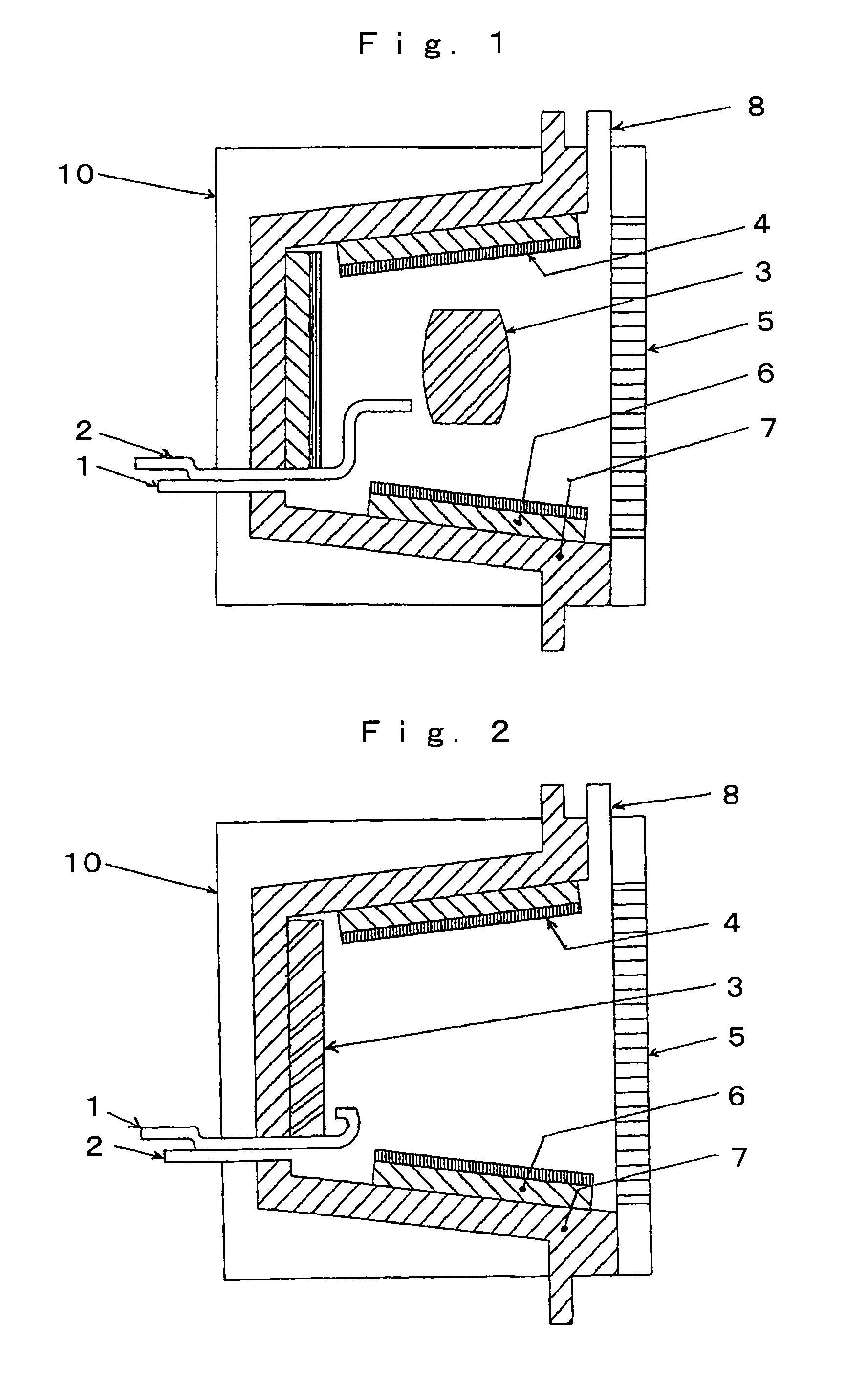
[0084]FIG. 1 is a cross-sectional view of an illumination device according to the present invention. This is an illumination device capable of simultaneously supplying light, heat, and electricity, which includes an air supply means 1, a gaseous fuel supply means 2, a combustion part 3, a reflector plate 4 provided around the combustion part 3, a translucent panel 5 installed in a part not surrounded by the reflector plate 4, a power generating element 6 installed in contact with whole or part of a rear surface of the reflector plate 4, a heat collecting means 7 provided on a rear surface of the power generating element 6, and an exhaust gas discharge means 8. An exterior cover of the illumination device will be called a case 10.

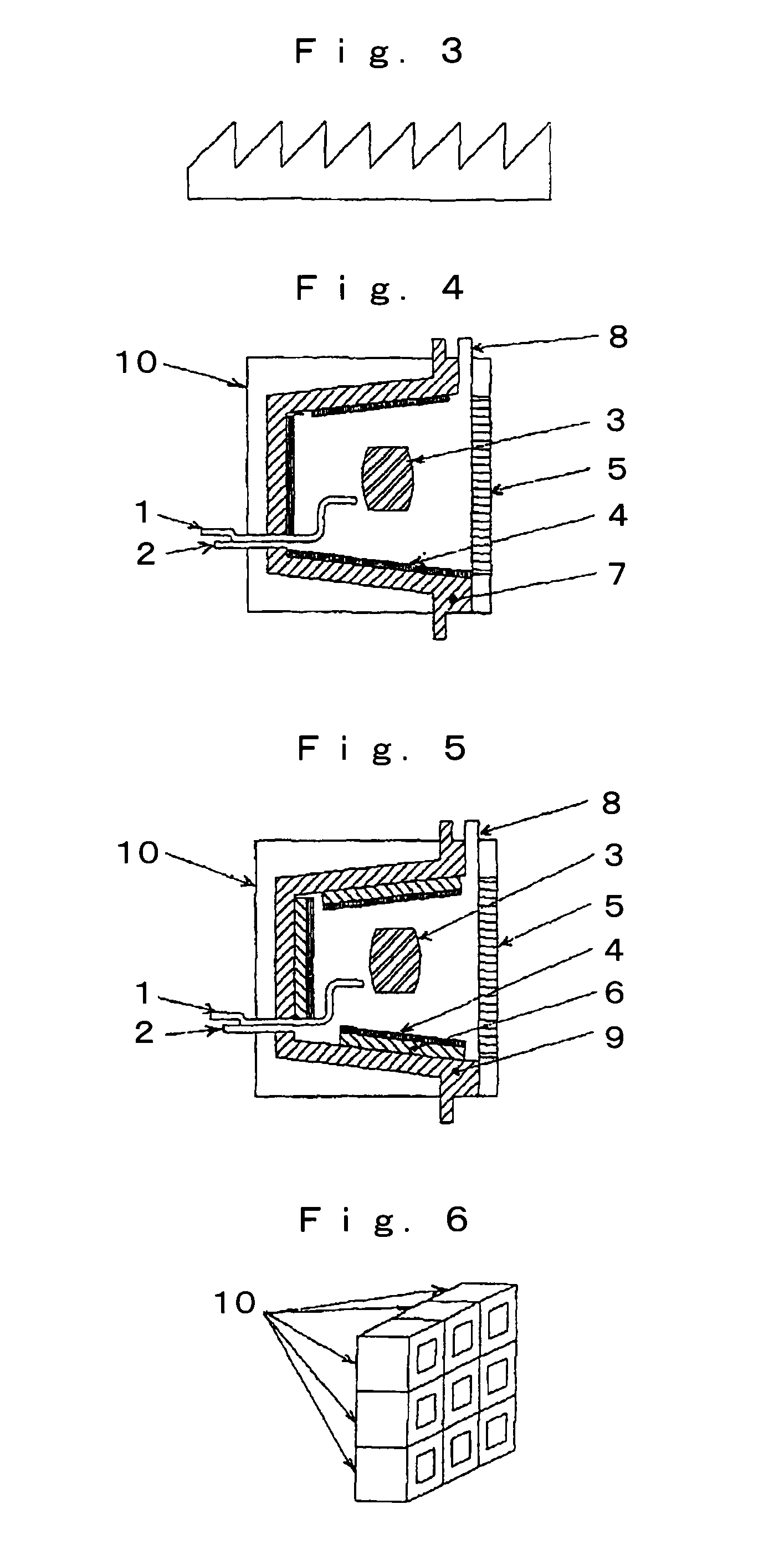
[0085]FIG. 4 is a cross-sectional view of an illumination device according to the present invention. This is an illumination device capable of simultaneo...


PUM


Abstract

An illumination device that can simultaneously supply visible light, heat, and electricity, or visible light and heat, or visible light and electricity. A reflector plate, which has properties of reflecting visible rays and transmitting or absorbing heat rays, and a translucent panel, which has properties of transmitting visible rays and reflecting heat rays, efficiently split combustion light generated by high-brightness catalytic combustion fueled with combustible gaseous substance such as city gas, and a thermoelectric element converts heat into electricity. Thereby, effective energy use is realized.

Description

TECHNICAL FIELD[0001]The present invention relates to a device which simultaneously supplies visible light, heat, and electricity, or visible light and heat, or visible light and electricity, from catalytic combustion fueled with combustible gaseous substance such as city gas.BACKGROUND ART[0002]Conventionally, fluorescent lights, incandescent lights, and the like using electric energy have been used for indoor illumination. In such illumination, about 5 to 20% of the electric energy input for the illumination is converted into light energy.[0003]Here, in most cases, the electric energy is supplied from a grid of an electric power company, and it is estimated that this electric energy at a customer's premise is about 36.6% of the energy input at a power plant of the electric power company since a heat loss at the power plant and a power transmission loss is deducted from the input energy (according to a subsidy application manual for the Energy Saving Law prepared by NEDO).[0004]Thi...

Claims


Application Information

Patent Timeline
IPC IPC(8): F21L19/00
CPCF21S9/04F21S13/00F21V33/00F21W2131/40F21V2200/13F23D14/18F23M2900/13003H01L35/00F21W2131/407F23D14/181H10N10/00
Inventor MABUCHI, TOSHIHIKO
Owner MABUCHI TOSHIHIKO
Learn More