Ink jet printing apparatus and printing method

Inactive Publication Date: 2009-10-29
CANON KK
View PDF5 Cites 4 Cited by
  • Summary
  • Abstract
  • Description
  • Claims
  • Application Information

AI Technical Summary

Benefits of technology

[0013]An object of the present invention is to solve the foregoing problem, that is, to make an ink dot formed by a preliminary ejection less noticeable, and to reduce the influence on the printing quality even in a case where an ink of low lightness is preliminarily ejected onto an image area of high lightness.
[0020]In the present invention, in a case where an ink of low lightness is preliminarily ejected onto a color image area of high lightness, the amount of the color ink to be applied for printing the area is reduced. This reduces an area where the ink dot formed by the preliminary ejection overlaps the light color image area. Thus, it is possible to make the ink dot formed by the preliminary ejection less noticeable, and to reduce the influence on the printing quality.

Problems solved by technology

As a result, in some cases, ink is not ejected properly from such a nozzle, even when a drive signal is applied to an element generating energy used for ejecting the ink.
This causes a deflection of the ejecting direction, and allows only an insufficient amount of ink to be ejected, or in extreme cases, ink is not ejected at all (hereinafter, these poor conditions are called an ejection failure).
As a result, a desired image cannot sometimes be obtained.
In particular, this operation is aimed at ejecting, from a nozzle, ink in an inadequate condition to secure the ejection performance and printing quality when the partial evaporation of volatile constituents such as water or solvent contained in the ink results in the inadequate condition.
In this case, however, the printing head is required to move away from the printing area, but this movement needs a longer time of suspending the printing operation.
As a result, the throughput of printing decreases.
Accordingly, when an ink dot with a certain size and a certain density is formed on the printing medium with the ink of the preliminary ejection, the ink dot may be noticeable, and may deteriorate the printing quality.
Nevertheless, in the circumstance in which various kinds of printing are performed to meet the demands of users as the use of ink jet printing apparatuses being increasing, a printing image does not necessarily include an area with a high optical reflection density, such as a black letter.
However, a problem arises here.
This results in the deterioration in the printing quality.
This problem arises not only in the relationship between yellow and cyan, but also in a case where a dark color ink, such as a magenta ink or a black ink, is preliminarily ejected onto an image area formed with the yellow ink.
This problem also arises in a case where an ink of low lightness is preliminarily ejected onto an area printed with any of these light color inks.

Method used


Image

  • Ink jet printing apparatus and printing method
  • Ink jet printing apparatus and printing method
  • Ink jet printing apparatus and printing method

Examples


first embodiment

2.1 First Embodiment

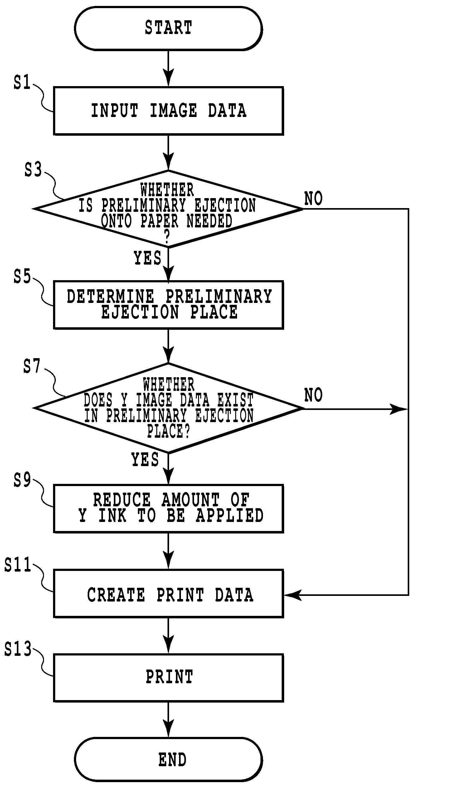
[0049]In this Embodiment, in a case where a yellow ink dot exists in a position onto which a cyan ink is to be preliminarily ejected, the amount of yellow ink to be applied is reduced by deleting a piece of image data for forming the yellow ink dot.

[0050]FIGS. 4A to 4D are explanatory diagrams for this embodiment.

[0051]As shown in FIG. 4A, firstly, assume that there is a yellow (Y) ink image data covering an area extending from the coordinates n to n+2 in the main-scan direction and from the coordinates m to m+1 in a sub-scan direction. Then, assume that a cyan (C) ink is to be preliminarily ejected into the set of coordinates (n+1, m+1) inside the above area, as shown in FIG. 4B.

[0052]In this case, in this embodiment, print data is formed by deleting a piece of data for forming the yellow ink dot in the set of coordinates (n+1, m+1) so that only the cyan ink dot is formed in the point, as shown in FIG. 4C. As a result, the cyan ink dot is landed on the set of co...

second embodiment

2.2 Second Embodiment

[0053]In this Embodiment, even in a case where a yellow ink dot exists not in a position where a cyan ink is to be preliminarily ejected, but around the position, the amount of yellow ink to be applied is reduced by thinning image data for forming the surrounding yellow ink dots.

[0054]FIGS. 5A to 5D are explanatory diagrams for this embodiment.

[0055]As shown in FIG. 5A, firstly, assume that there is a yellow (Y) ink image data, except for the set of coordinates (n+1, m+1), covering an area extending from the coordinates n to n+2 in a main-scan direction and from the coordinates m to m+1 in a sub-scan direction. Then, assume that a cyan (C) ink is to be preliminarily ejected into the set of coordinates (n+1, m+1) inside the above area, as shown in FIG. 5B.

[0056]In this embodiment, the pieces of data deleted in this case are those for forming the dots in the sets of coordinates (n+1, m) and (n+1, m+2), both of which are adjacent to the preliminary ejection coordin...

third embodiment

2.3 Third Embodiment

[0058]In this Embodiment, in a case where a yellow ink dot exists in a position where a cyan ink is to be preliminarily ejected, and where yellow ink dots also exist around the position, the amount of yellow ink to be applied is reduced by thinning image data for forming the yellow ink dots.

[0059]FIGS. 6A to 6D are explanatory diagrams for this embodiment.

[0060]As shown in FIG. 6A, first, assume that there is a yellow (Y) ink image data covering an area extending from the coordinates n to n+2 in a main-scan direction and from the coordinates m to m+1 in a sub-scan direction. Then, assume that a cyan (C) ink is to be preliminarily ejected into the set of coordinates (n+1, m+1) inside the above area, as shown in FIG. 6B.

[0061]In this embodiment, the pieces of data deleted in this case are those for forming the yellow ink dots in the sets of coordinates (n+1, m) , (n+1, m+2), (n, m+1) and (n+2, m+1) in addition to the set of coordinates (n+1, m+1) of the preliminary...


PUM


Abstract

A dark color (for example, cyan) ink dot formed by preliminary ejection can be made less noticeable, and the influence on the printing quality can be reduced, even in a case where the dark color ink is preliminarily ejected onto a light color (for example, yellow) image area. For this purpose, in a case where the dark color ink is preliminarily ejected onto the image area of high lightness, the amount of the ink applied for printing the area is reduced. For example, in a case where a cyan ink is preliminarily ejected onto an area to be formed of yellow dots, a piece of data for forming the yellow dot in the preliminary ejection position is deleted. This reduces an overlapping area of the yellow area and the ink dot formed by the preliminary ejection, and thus makes the ink dot formed by the preliminary ejection less noticeable.

Description

TECHNICAL FIELD[0001]The present invention relates to an ink jet printing apparatus and a printing method.BACKGROUND ART[0002]In an ink jet printing apparatus, generally, not all print data use all the plurality of nozzles provided on a printing head, and there is a case where a particular nozzle is not used for a long time. Water or solvent in such a nozzle evaporates, and thus the viscosity thereof increases. As a result, in some cases, ink is not ejected properly from such a nozzle, even when a drive signal is applied to an element generating energy used for ejecting the ink. This causes a deflection of the ejecting direction, and allows only an insufficient amount of ink to be ejected, or in extreme cases, ink is not ejected at all (hereinafter, these poor conditions are called an ejection failure). As a result, a desired image cannot sometimes be obtained.[0003]An operation called a preliminary ejection is performed as one of treatments for eliminating the factors causing the e...

Claims


Application Information

Patent Timeline
IPC IPC(8): B41J29/38
CPCB41J19/147
Inventor TSUCHII, KEN
Owner CANON KK
Why Eureka
Try Eureka