
Steering control apparatus

a control apparatus and steering technology, applied in the direction of dynamo-electric converter control, motor/generator/converter stopper, stopping arrangement, etc., can solve problems such as mechanical switch malfunctions, and achieve the effect of low cos

Active Publication Date: 2009-10-29
JTEKT CORP
View PDF12 Cites 19 Cited by
  • Summary
  • Abstract
  • Description
  • Claims
  • Application Information

AI Technical Summary

Benefits of technology

[0007]An object of the invention is to provide, at low cost, a steering control apparatus capable of disconnecting a motor driving circuit from a three-phase alternating current motor reliably when an abnormality occurs.
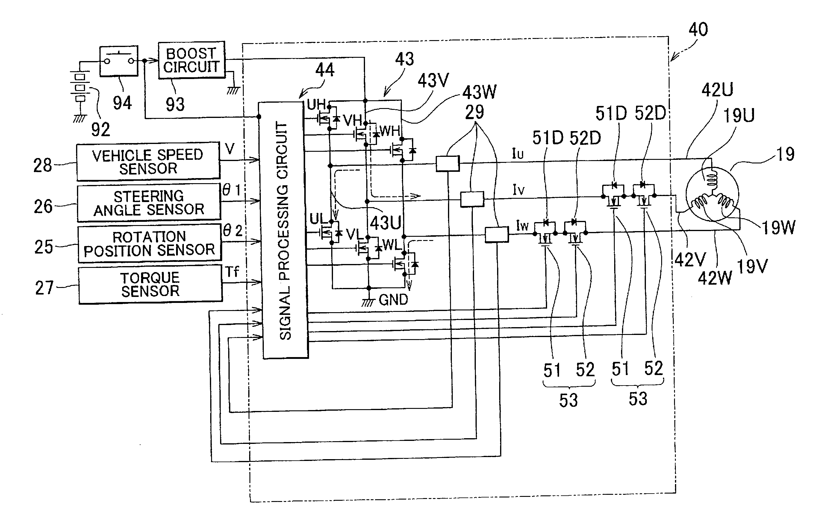
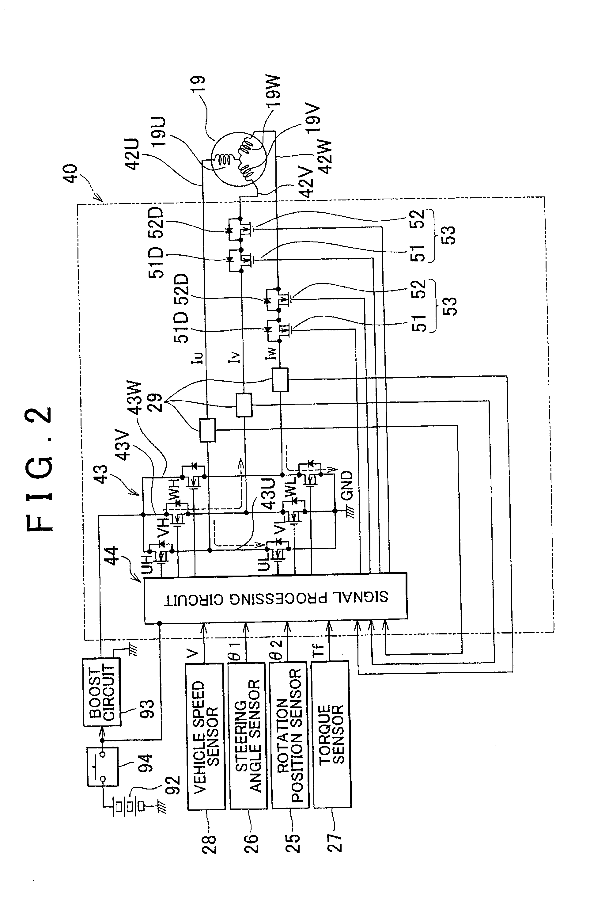
[0011]When an abnormality occurs during conduction of the three-phase alternating current between the motor driving circuit and the three-phase alternating current motor, the MOSFETs through which no current is flowing or the MOSFETs through which a current oriented to turn the parasitic diodes on is flowing are sequentially turned off such that all of the emergency switching elements are turned off. Here, even when the MOSFETs through which a current oriented to turn the parasitic diodes on is flowing are turned off, rapid current blocking does not occur, and therefore a spike voltage is not generated. Needless to say, a spike voltage is not generated when the MOSFETs through which no current is flowing are turned off. Hence, there is no need to use expensive MOSFETs that can withstand a spike voltage as the emergency switching elements, and therefore a reduction in cost can be achieved. In other words, according to the first embodiment, a steering control apparatus that is capable of disconnecting a motor driving circuit and a three-phase alternating current motor reliably when an abnormality occurs can be provided at low cost.
[0014]Further, in the second embodiment, the MOSFET serving as the emergency switching element is provided singly in all three phases of the three-phase power supply line, and the parasitic diodes of the MOSFETs are disposed in an identical orientation relative to the three-phase alternating current motor. Hence, when the emergency switching elements are all turned off, a conductive closed circuit partially including a three-phase phase circuit of the three-phase alternating current motor ceases to exist, and therefore power generation resistance of the three-phase alternating current motor is removed, enabling a reduction in, steering resistance when an abnormality occurs.
[0015]When an abnormality occurs during conduction of the three-phase alternating current between the motor driving circuit and the three-phase alternating current motor, the MOSFETs through which no current is flowing or the MOSFETs through which a current oriented to turn the parasitic diodes on is flowing are sequentially turned off such that all of the emergency switching elements are turned off. Here, even when the MOSFETs through which a current oriented to turn the parasitic diodes on is flowing are turned off, rapid current blocking does not occur, and therefore a spike voltage is not generated. Needless to say, a spike voltage is not generated when the MOSFETs through which no current is flowing are turned off. Hence, there is no need to use expensive MOSFETs that can withstand a spike voltage as the emergency switching elements, and therefore a reduction in cost can be achieved. In other words, according to the second embodiment, a steering control apparatus capable of disconnecting a motor driving circuit and a three-phase alternating current motor reliably when an abnormality occurs can be provided at low cost.

Problems solved by technology

In this steering control apparatus, the mechanical switch is turned off when an abnormality occurs such that a motor driving circuit provided in the steering control apparatus is disconnected from the steering assist motor.
However, a malfunction may occur in the mechanical switch due to the infiltration of foreign matter.

Method used


Image

  • Steering control apparatus
  • Steering control apparatus
  • Steering control apparatus

Examples


first embodiment

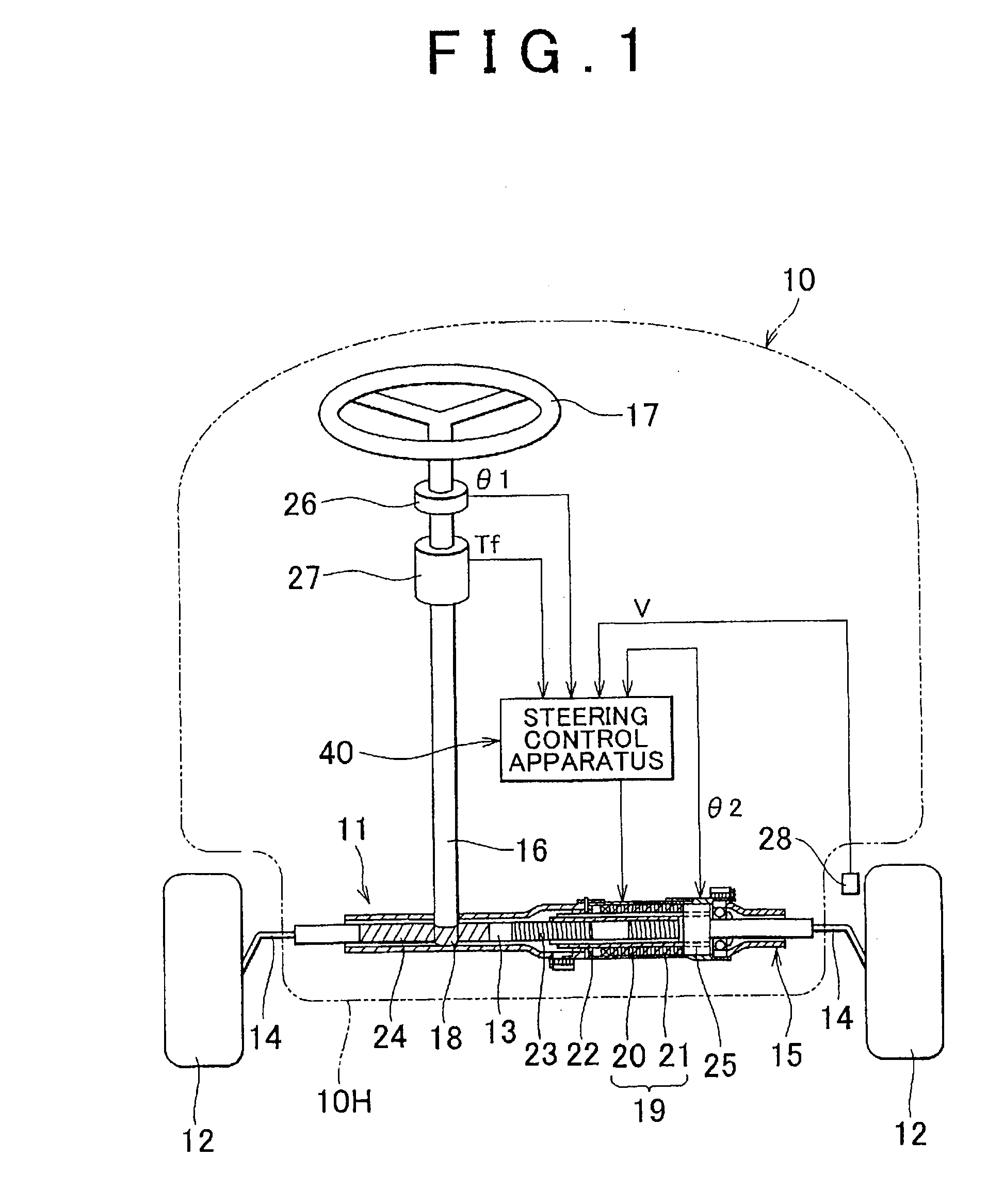
[0028]A first embodiment of the invention will be described below on the basis of FIGS. 1 to 5. FIG. 1 shows a vehicle 10 installed with an electric power steering apparatus 11. The electric power steering apparatus 11 includes a shaft 13 that is provided between steered wheels so as to extend in a left-right direction of the vehicle 10, and the shaft 13 provided between the steered wheels is inserted into a core of a tubular housing 15 fixed to a vehicle main body 1OH. Further, the two ends of the shaft 13 provided between the steered wheels are connected to respective steered wheels 12, 12 via tie rods 14, 14.

[0029]A three-phase alternating current motor 19 (to be referred to simply as a “motor 19” hereafter) serving as a driving source of the electric power steering apparatus 11 is a three-phase alternating current motor having a hollow tubular structure, for example. A stator 20 of the motor 19 is fixed within the tubular housing 15, and the shaft 13 provided between the steered...


PUM


Abstract

A steering control apparatus includes a direct current power source, a three-phase alternating current motor, and a motor driving circuit. An emergency switching element is provided on at least two phases of a three-phase power supply line connected to the three-phase alternating current motor within the motor driving circuit, and the emergency switching element is turned off when an abnormality occurs such that the motor driving circuit is disconnected from the three-phase alternating current motor. The emergency switching element is a MOSFET, and the MOSFETs are provided in pairs in each of the two phases of the three-phase power supply line. Further, parasitic diodes of the pairs of MOSFETs are disposed in opposite orientations to each other.

Description

INCORPORATION BY REFERENCE[0001]The disclosure of Japanese Patent Application No. 2008-112011 filed on Apr. 23, 2008 including the specification, drawings and abstract is incorporated herein by reference in its entirety.BACKGROUND OF THE INVENTION[0002]1. Field of the Invention[0003]The invention relates to a steering control apparatus for assisting steering of a steering wheel by driving a three-phase alternating current motor, that is referred to hereafter as a “steering assist motor”, serving as a driving source of an electric power steering apparatus.[0004]2. Description of the Related Art[0005]In this type of steering control apparatus, when the steering assist motor cannot be driven due to an abnormality, the steering assist motor is rotated by the steering of the steering wheel so as to function as a power generator, and as a result, a battery as direct current power source of a vehicle, for example, is charged. Steering resistance generated at this time includes both frictio...

Claims


Application Information

Patent Timeline
Patent Type & Authority Applications(United States)
IPC IPC(8): H02H7/08
CPCH02P6/24B62D5/0484
Inventor SHIBATA, YOSHIYUKI
Owner JTEKT CORP
Learn More