
Rotating drill pipe protector attachment and fastener assembly

a technology of protector applied in the direction of drilling rods, drilling casings, drilling pipes, etc., can solve the problems of significant torque and drag, and wear of both casings and drill pipes, and achieve the effect of preventing buckling of drill pipes and substantial gripping strength

Inactive Publication Date: 2009-10-29
WWT NORTH AMERICA HLDG
View PDF60 Cites 18 Cited by
  • Summary
  • Abstract
  • Description
  • Claims
  • Application Information

AI Technical Summary

Benefits of technology

[0016]After closing and rotating the fasteners into engagement with the hinge bar receptor sections, the fasteners are tightened to produce a holding force around the drill pipe that is much greater than the wedge pin method commonly found in current RDPPs. In one embodiment, the hinged rotating protector of this invention, tightened around a drill pipe at 25 ft-lbs., produces a gripping strength that resists axial slippage at applied loads greater than 10,000 ft-lbs.
[0017]In other embodiments, the rotating drill pipe protector of this invention, because of its substantial gripping strength, can be used in applications for preventing buckling of drill pipe.

Problems solved by technology

When drilling oil and gas wells with rotary drilling equipment, the drill pipe frequently comes into contact with the well casing, resulting in wear to both the casing and the drill pipe.
In addition, the friction between the drill pipe and casing may result in significant torque and drag, which can exceed the capability of the rig's drive system.
Low grip strength around the pipe can frequently result in the protector slipping on the pipe; and when the protectors move away from their installed position, they become ineffective at preventing wear.
Also, problems are caused by the inability to strip through pressure control equipment, such as diverter assemblies, rotating pressure control heads, and BOPs, due to low grip strength.
Once the protector has slipped, its structural integrity is too often inadequate to prevent serious failure of the protector, resulting in debris in the well.
The previously mentioned stamped steel wedge pin design produces low holding forces and leaves a significant portion of the pin remaining above the protector where it can hang-up on obstructions.
A frequent problem offshore is in drilling with a riser in deep water.
Drill pipe in these conditions may wear the riser, well head, and BOP equipment at significant cost and rig downtime.
However, this is an extremely demanding application, requiring large holding forces for RDPPs.
Buckling of drill pipe has been and remains a serious problem to drilling by reducing the drilling penetration, damaging drill pipe, and sometimes preventing reaching the reservoir.
The use of non-rotating drill pipe protectors to prevent buckling has been successful in increasing the buckling load, but at a cost.
First, non-rotating drill pipe protectors are expensive and can be subject to damage because of the extremely high side loads at or near buckling.
Rotating protectors are typically not used to prevent buckling.
The reason is that existing rotating drill pipe protectors have poor gripping capability and cannot withstand the loads seen at or near buckling.

Method used


Image

  • Rotating drill pipe protector attachment and fastener assembly
  • Rotating drill pipe protector attachment and fastener assembly
  • Rotating drill pipe protector attachment and fastener assembly

Examples


Embodiment Construction

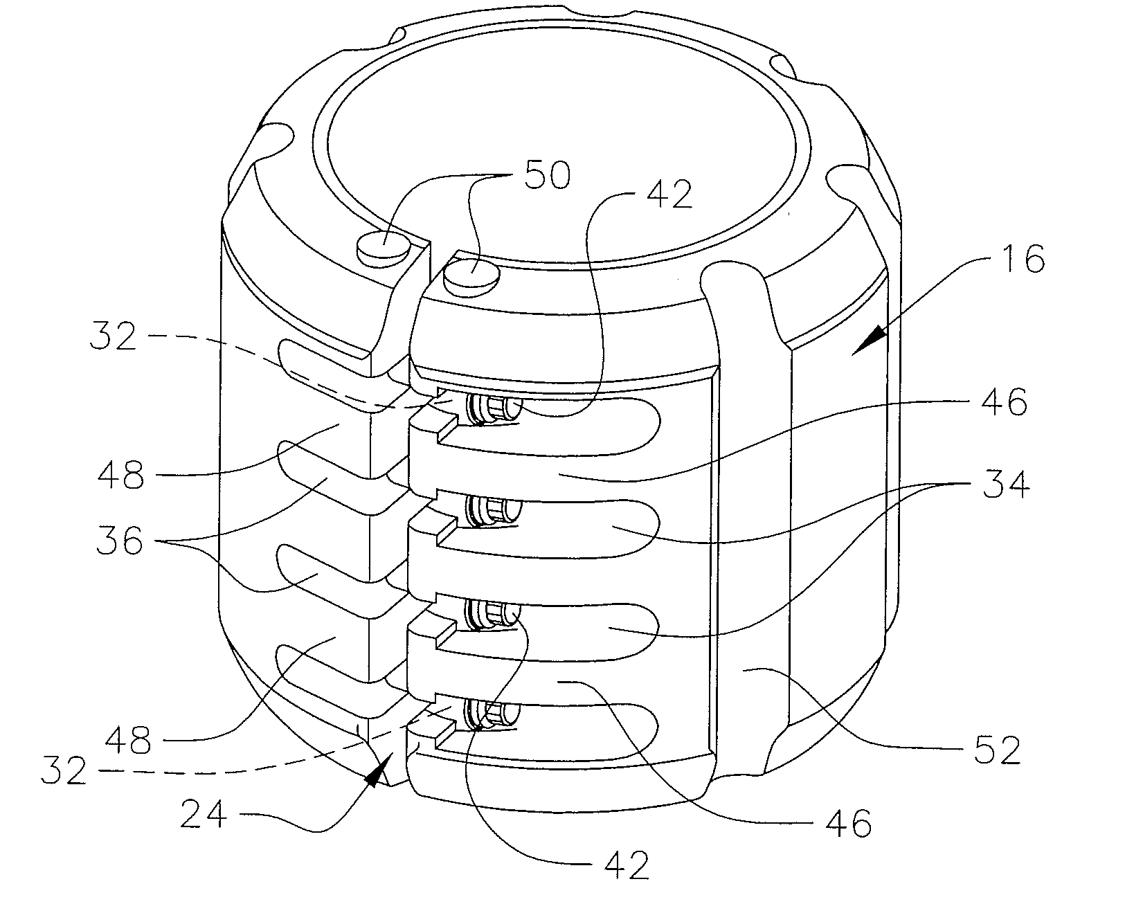
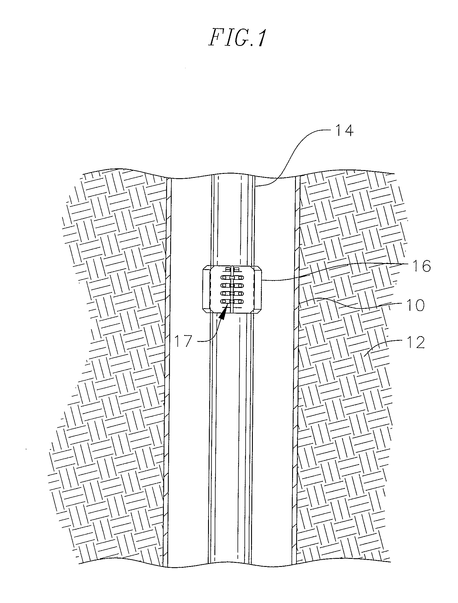
[0031]FIG. 1 illustrates a well bore comprising a casing 10 in an underground formation 12 during oil well drilling operations. This is one illustrated use of the invention which also can be used in under water drilling operations. A rotating drill pipe 14 in the casing or well bore has a drill bit (not shown) at the bottom, for drilling the well bore. A rotating drill pipe protector (RDPP) 16 is secured to the drill pipe for protecting the drill pipe and casing from abrasion damage during use, as is well known in the art.

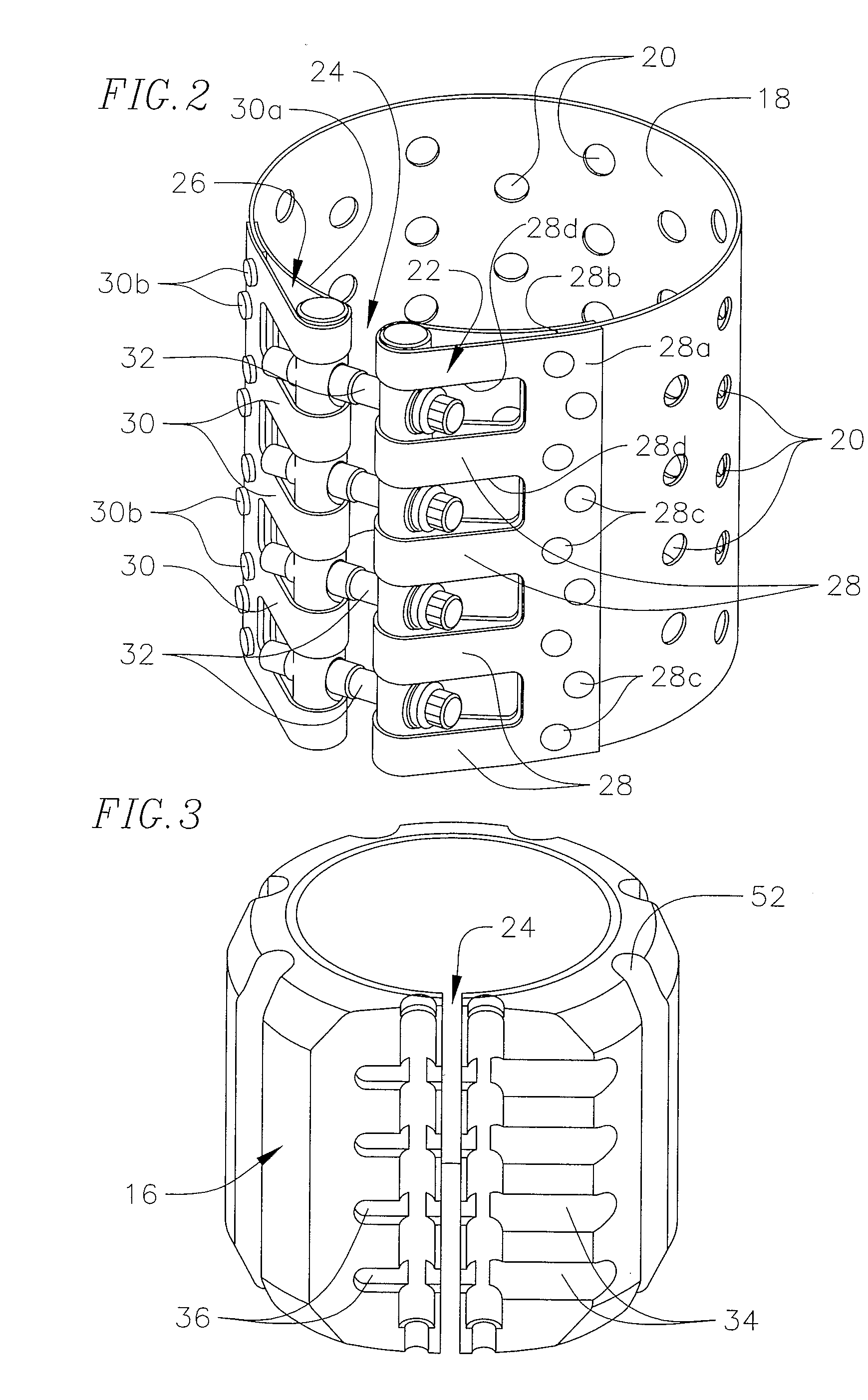
[0032]Generally speaking, the rotatable drill pipe protector 16 comprises an elongated cylindrical sleeve made from a protective low friction material which is molded into its desired configuration around an internal reinforcing cage structure, as described below. The sleeve is fastened to the drill pipe by an attachment and fastener assembly 17 for securing the sleeve in a fixed stationary position on the drill pipe. The exterior of the sleeve preferably includes ...


PUM


Abstract

An attachment and fastener system rigidly secures a rotatable drill pipe protector (RDPP) to a drill pipe. The RDPP comprises a sleeve which is split axially along at least one side. Parallel hinge bars are contained in first and second hinge sections which wrap around the hinge bars along opposite sides of the opening in the RDPP. One hinge bar is rotatable in the first hinge section. A series of axially spaced apart bolts are held in corresponding threaded openings in the rotatable hinge bar which rotates about its axis to swing the bolts in unison between open and closed positions. The other hinge bar has a series of threaded receptor openings facing outwardly from slotted openings in the second hinge section and aligned with the bolts on the other hinge bar. The rotating hinge bar swings the bolts into alignment with the slotted openings in the other hinge, after which the bolts are tightened in the threaded receptor openings for applying a holding force around the drill pipe. The hinges which wrap around each hinge bar are formed on the ends of a reinforcing cage structure molded into the wall of the RDPP.

Description

CROSS-REFERENCE TO RELATED APPLICATION[0001]This application claims the benefit of and priority to U.S. Provisional Application No. 61 / 125,547, filed on Apr. 24, 2008, the entire disclosure of which, including the appendix, is fully incorporated herein by this reference.FIELD OF THE INVENTION[0002]This invention relates to wear protectors for rotating drill pipes used in oil and gas exploration or recovery, and more particularly to rotating drill pipe protectors, those that are fixed to the rotating drill pipe and rotate with the drill pipe during use.BACKGROUND OF THE INVENTION[0003]When drilling oil and gas wells with rotary drilling equipment, the drill pipe frequently comes into contact with the well casing, resulting in wear to both the casing and the drill pipe. In addition, the friction between the drill pipe and casing may result in significant torque and drag, which can exceed the capability of the rig's drive system. Drill pipe protectors are commonly known in the industry...

Claims


Application Information

Patent Timeline
Patent Type & Authority Applications(United States)
IPC IPC(8): E21B17/10E21B7/00
CPCE21B17/105
Inventor MITCHELL, SARAH B.KRUEGER, IV, RUDOLPH ERNSTCASASSA, GARRETT C.
Owner WWT NORTH AMERICA HLDG
Learn More