
Door Operator for Controlling a Door and Method of Same

a door operator and door technology, applied in the direction of electric controllers, motor/generator/converter stoppers, dynamo-electric converter control, etc., can solve problems such as perceived deficiencies in the ar

Active Publication Date: 2009-10-29
ASSA ABLOY ACCESSORIES & DOOR CONTROLS GRP INC
View PDF76 Cites 95 Cited by
  • Summary
  • Abstract
  • Description
  • Claims
  • Application Information

AI Technical Summary

Benefits of technology

The present invention is a door operator that improves the operation of doors by using a motor to open the door against a spring force. The operator includes a door position sensor and a controller that receives the sensor's signal and determines the door position and speed. The controller then measures the time it takes for the door to reach its predetermined angle and calculates the net torque acting on the door based on the spring force and the motor force. The net torque is used to determine the door's moment of inertia. The invention also includes a nonvolatile door position sensor and a controller that adjusts the braking load to control the door's closing speed. Additionally, the invention includes a door operator assembly with a roller clutch for disengaging the motor during manual door opening and engaging it on door closing or power opening. The technical effects of the invention include improved door operation and control over door speed and position.

Problems solved by technology

However, it is believed that the state of the art has perceived deficiencies.

Method used


Image

  • Door Operator for Controlling a Door and Method of Same
  • Door Operator for Controlling a Door and Method of Same
  • Door Operator for Controlling a Door and Method of Same

Examples


first embodiment

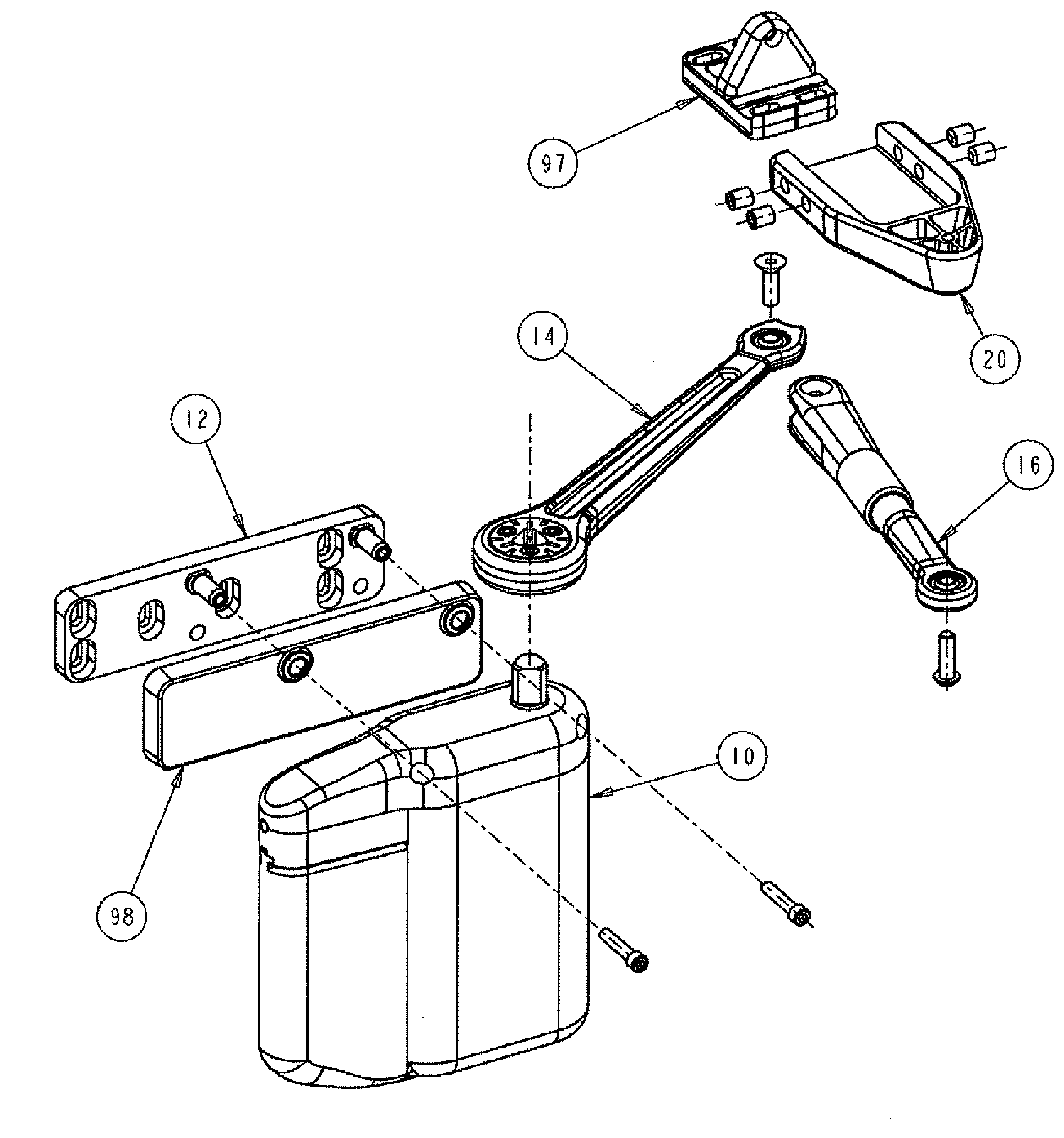
[0054]For example, in accordance with a first embodiment, a door operator for controlling operation of a door is provided, the door operator having a motor to open the door against a spring force, said door operator further comprising a door position sensor for transmitting a signal indicative of door position; and a controller for controlling a motor current to generate a predetermined motor force to open the door to a predetermined angle; receiving the signal from the door position sensor and determining a door position and a door speed based on the signal; measuring the time for the door to reach the predetermined angle from a closed position; measuring the current to hold the door at the predetermined angle; converting the measured current to an equivalent force of the motor acting on the spring, which represents the spring force; determining a first torque value acting on the door based on the spring force; determining a second torque value acting on the door based on the prede...

second embodiment

[0093]In a second embodiment a directional mechanical override clutch is used to engage a when a door opens at an excessive speed.

[0094]At the start of closing the invention applies a force proportional to the force available in the compressed spring and the door is allowed to accelerate as fast as it can. However when the closing speed is close to a desired maximum closing speed for the door, the invention switches into a regenerative mode where excess kinetic energy in the door, is converted into electrical energy by motor 10 acting as a generator to charge battery pack 18. Battery pack 18 may comprise one or more batteries as would be understood in the art. Therefore, reference to a battery or batteries will be understood to be a battery pack, and visa versa.

[0095]Power is supplied to motor 30 by a low voltage power storage pack 18 comprising rechargeable batteries. Recharging is accomplished by capturing excess energy during door closing in both manual and automatic modes and, i...


PUM


Abstract

A door operator for controlling operation of a door, the door operator having a motor to open the door against a spring force, the door operator further comprising a door position sensor for transmitting a signal indicative of door position; and among other things, calculates a door moment of inertia based on a net torque and the time for the door to reach a predetermined angle from the closed position. Also provided is a door operator that compares door speed to a desired door speed based on a door speed-position profile and generates a door speed error signal and minimizes the door speed error signal by adjusting the braking load resulting from charging a chargeable battery using the motor as a generator.

Description

CROSS-REFERENCES TO RELATED APPLICATIONS[0001]This application is a continuation-in-part of U.S. application Ser. No. 11 / 403,490, filed Apr. 13, 2006, which claims the benefit of U.S. Provisional Application No. 60 / 751,623 filed Apr. 13, 2005. All of the subject matter and disclosure of the aforementioned U.S. application Ser. No. 11 / 403,490 and U.S. Provisional Application No. 60 / 751,623 are incorporated by reference as if each are fully set forth herein.BACKGROUND OF THE INVENTION[0002]The present invention is directed to door operators for controlling a door and methodology for controlling the door.[0003]The prior art contains at least several patents related to door closers. For example, U.S. Pat. No. 4,973,894 to Johansson describes what the inventor therein characterizes as a method and arrangement for optimizing the operation of a door closer at different phases of opening and closing of the door. In particular, this '894 patent describes that the door closer is provided with...

Claims


Application Information

Patent Timeline
Patent Type & Authority Applications(United States)
IPC IPC(8): E05F15/10G05B11/42
CPCE05Y2201/686E05F15/63E05Y2400/36E05Y2400/456E05Y2400/612E05Y2400/614E05Y2800/112E05Y2800/113E05Y2800/252E05Y2800/372E05Y2800/40E05Y2900/132E05F1/105E05F3/224E05Y2201/41E05Y2201/604E05Y2400/32E05Y2400/342E05Y2800/00E05Y2900/00E05F3/227E05Y2400/628E05Y2400/302E05Y2800/176E05F15/40E05Y2400/3015E05Y2400/3014
Inventor HASS, BRIANDUBE, ERIC
Owner ASSA ABLOY ACCESSORIES & DOOR CONTROLS GRP INC
Learn More