
Self-powered coordinate probe

a technology of coordinate probes and probe heads, applied in the field of measuring probes, can solve the problems of difficult realization, fastidious and time-consuming, and often problematic power supply of such probe heads, and achieve the effect of maximising the effect of existing mechanical energy and improving overall system efficiency

Inactive Publication Date: 2009-10-29
HEXAGON TECH CENT GMBH
View PDF6 Cites 64 Cited by
  • Summary
  • Abstract
  • Description
  • Claims
  • Application Information

AI Technical Summary

Benefits of technology

[0014]The proposed solution first improves the overall system efficiency in terms of power consumption. Transforming energy already produced by the machine, storing and reusing it into another form, dispenses indeed with the use of any additional energy source; furthermore, since no power autonomy problem is encountered at the machine side, the mechanical energy delivered on the probe is theoretically not bounded. The use of a flywheel as a primary energy source hence maximises the effects of the existing mechanical energy of the system in turning it into electrical power generation.
[0016]Further advantages of the provided solution are its convenience and simplicity of use, as well as an almost maintenance-free operation.

Problems solved by technology

The power supply for such probe heads is often problematic, insofar as the shanks to which the probes' housings are attached usually do not contain any electrical energy source or electrical connections.
The limited lifetime of the batteries requires though their regular recharging and / or manual replacement, which is fastidious and time-consuming.
This is not easily realized and involves a particular design of the tool-holder.

Method used


Image

  • Self-powered coordinate probe
  • Self-powered coordinate probe
  • Self-powered coordinate probe

Examples


Embodiment Construction

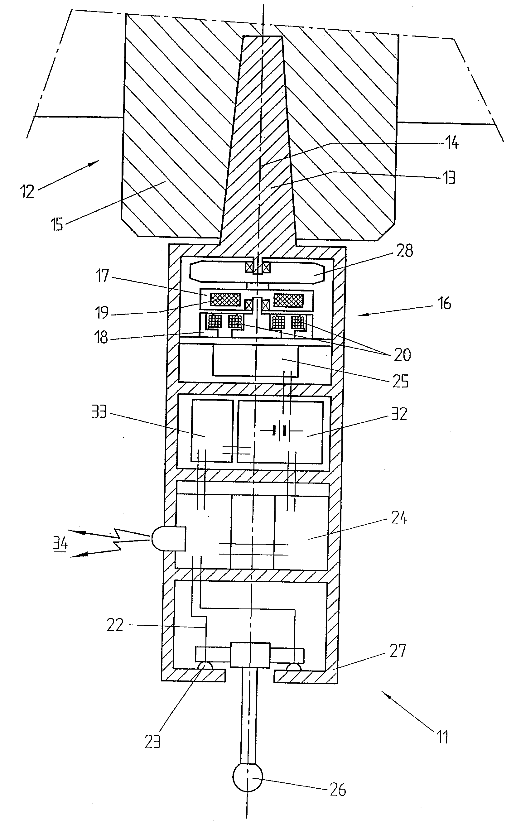
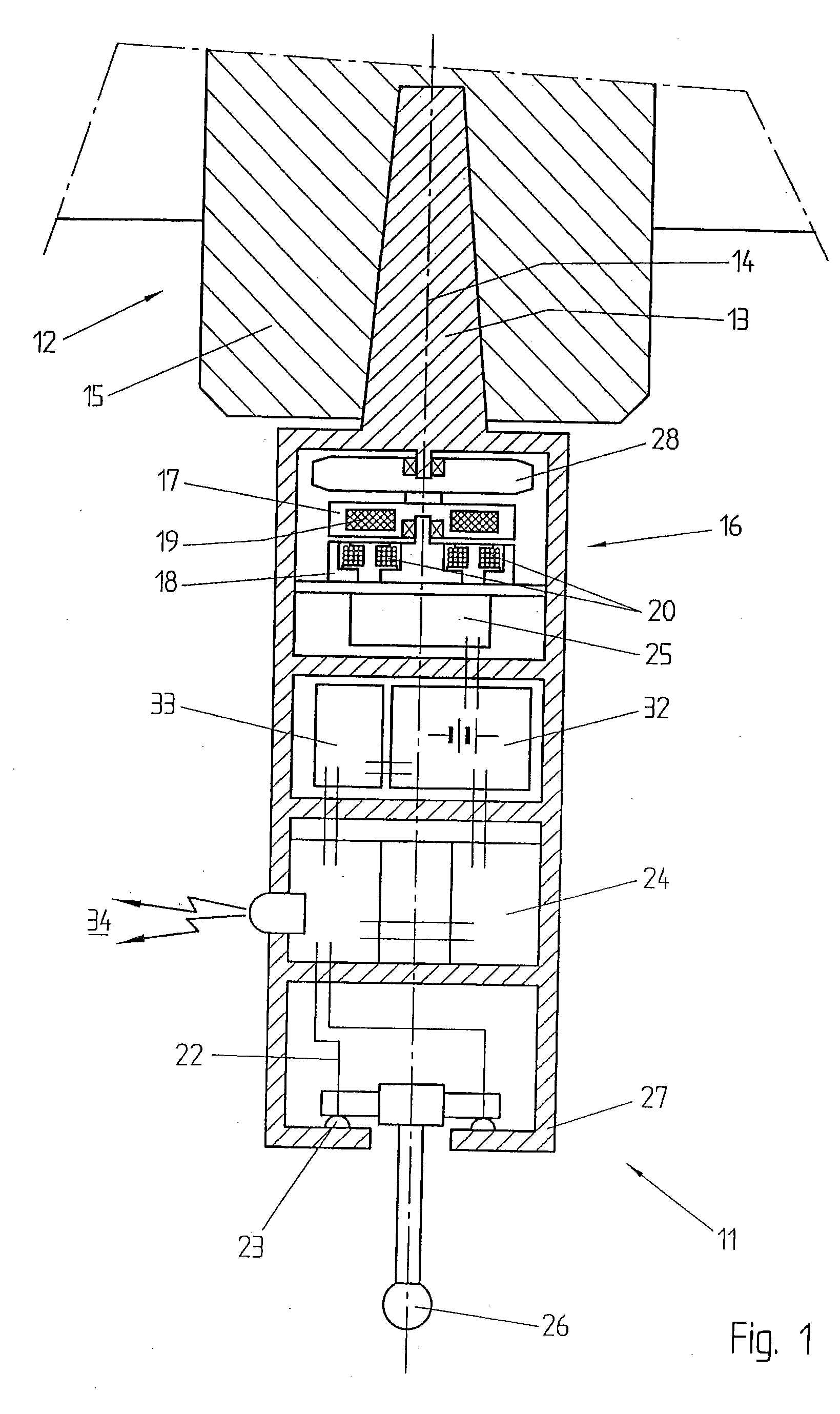
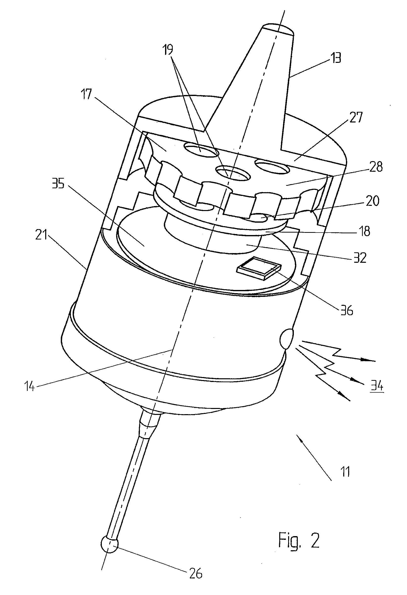
[0024]FIG. 1 illustrates a section of a probe 11 according to a preferred embodiment and example of use of the invention. We will assume, for sake of simplicity, that the probe 11 is used in a conventional CNC milling machine 12 having three linear axis XYZ and a rotary spindle 15, though it must be understood that this is not a limitation of the present invention, which can be used in all manners of machine tools 12.

[0025]In the represented example the probe 11 is releasably secured to the spindle 15 of the machine tool 12 through a holder comprising a standard taper 13 compatible with the machine tool in use. In the figures the taper is drawn, for simplicity, as integral with the probe. It must be understood, however, that the probe of the invention is not limited to a particular style of connection. The tapered shank will, in general, be part of a detachable tool-holder, to allow interoperability with different machines. The spindle 15 is driven into rotation around the rotating ...


PUM


Abstract

A probe, connectable to a machine tool, having an electric generator (16), supplying an electric or electronic circuit (22) with electric power, and a driving element (28), capable of relative rotation with respect to the stator of the electric generator. The rotation axis of the driving element is preferably a symmetry axis of the probe itself. The driving element is not connected to any external energy source, and can be set in rotation simply by activating the rotary axis of the machine tool.Advantageously, the driving element of the present invention is not directly connected with any mobile element of the machine tool, but is either rotatably mounted on the probe itself, or fixed on the reference table of the machine tool. Importantly, the inventive probe requires no additional connections to the machine tool on which it is mounted, besides the connection to the rotary spindle, which can be realized with a conventional tool-holder with a standardised tapered shank. In this way the inventive probe is fully compatible with standard probes, and can be mounted and used with standard tool-holders, without any adaptation. The self-powering function of the probe can be activated simply by sending appropriate rotation instructions to the machine tools.

Description

[0001]This application claims priority of European Patent Application EP08155085 filed on Apr. 24, 2008.FIELD OF THE INVENTION[0002]The present invention relates to measuring probes for use with industrial machine tools or coordinate measuring machines and specially adapted to use in computerized numerically controlled (CNC) machine tools. In particular, the present invention deals with a self-powered tool for used for measuring purposes on a workpiece.TECHNICAL BACKGROUND[0003]Machines that have the capability of automatically substituting different types of tools in order to perform various machining or measuring operations on a workpiece are quite widespread and well-known in the art. Modular tools are simply releasably secured to the machine, which allows dispensing with the use of specific machines for each specific operation.[0004]Whenever such tools contain an electric circuit, power supply need to be provided to the circuit, or at least some form of releasable electrical con...

Claims


Application Information

Patent Timeline
IPC IPC(8): G01B5/016H02K7/18
CPCG01B2210/58G01B7/012
Inventor JORDIL, PASCALGABELLA, FRANCOIS
Owner HEXAGON TECH CENT GMBH
Learn More