[0013]The present invention provides spinal implants and methods for restricting flexion of spinal segments for the treatment of
discogenic pain and other spinal conditions, such as
spondylolisthesis, where a physician may desire to control segmental flexion. Systems according to the present invention include
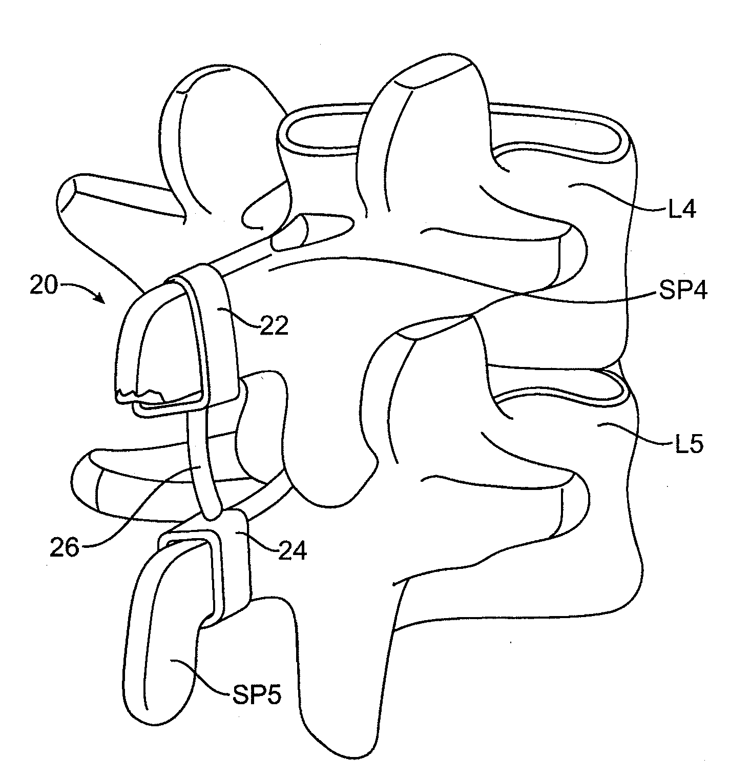
spinous process constraint structures comprising a first attachment element adapted to be placed over a first spinous process, a second attachment element adapted to be placed over a second spinous process, and a single connector joining the first attachment element and the second attachment element. By “single connector,” it is meant that the connector joins a
single point or location on the first attachment element to a
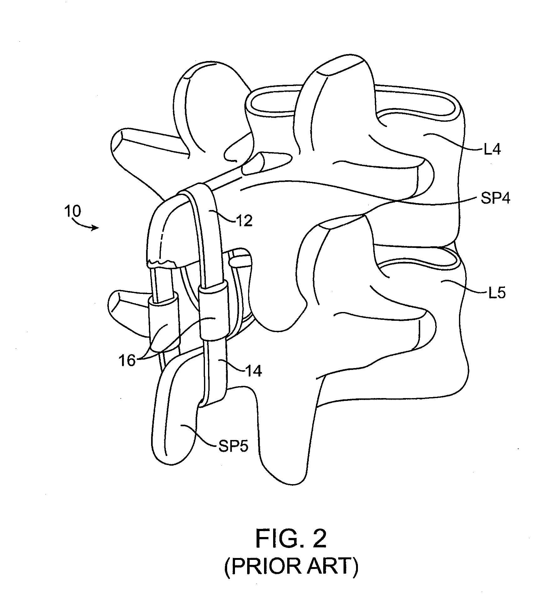
single point or location on the second attachment element. In contrast, the prior connectors shown in FIG. 2, for example, provide a pair of connection points and two connectors for joining the upper component 12 to the lower strap component 14. Use of the single connector for joining the first and second attachment elements reduces the likelihood that the attachment members will become displaced such that the desired symmetric attachment geometry becomes asymmetric. A single connector also reduces the need to balance the elastic forces being applied to the opposite sides of the spinous processes. The single connector will also simplify alignment of the
implant during implantation, thus simplifying
percutaneous implantation and potentially minimizing tissue disruption in both
percutaneous and other implantation protocols.
[0014]The single connector may comprise a single elastic member, where the single elastic member may itself comprise a continuous length of elastic material having uniform or non-uniform elastic properties along said length. Alternatively, the connector may comprise an elastic member including two or more separate components, for example inelastic or non-compliant straps, cables, or other flexible members attached to a compliance member which provides the desired elasticity. Different embodiments for the compliance members are described in co-pending, commonly owned application No. 12 / 106,103 (Attorney Docket No. 026398-000410US), filed on Apr. 18, 2008, the full disclosure of which is incorporated herein by reference. Regardless of the particular structure, the single connector and / or elastic member will provide an elastic stiffness in tension between the attachment members in the range from 7.5 N / mm to 50 N / mm, preferably from 10 N / mm to 25 N / mm, and usually in the range from 10 N / mm to 15 N / mm. In addition to providing such elastic stiffness in tension, the single connector and / or elastic member will be constructed to provide little or no elastic stiffness in compression. Usually, the elastic stiffness in compression will be below 3 N / mm, preferably below 0.5 N / mm. The ability of the constraint structures of the present invention to provide a targeted elastic stiffness in tension while providing little or no elastic stiffness in compression allows for treatment of patient's having spinal segments where the
kinematics are improved by application of the elastic force to the spine in flexion while providing little or no elastic resistance to extension.
[0018]In other instances, however, it will be desirable to position the single connector on a side of the spinous processes so that the connector does not need to pass through the region between the spinous processes. Such asymmetric constraint structures thus reduce or eliminate the need to penetrate the interspinous / supraspinous ligaments lessening patient trauma and facilitating placement protocols. For such asymmetric designs, the attachment member may be a simple pin, screw, or other
fastener which penetrates the body of the spinous process, but will more usually be a hook, loop, or other member which can attach to the spinous process without necessarily penetrating therethrough. For example, when using hooks, the upper attachment member can be placed over a superior surface of the superior spinous process while a lower hook member may be placed around the inferior surface of the inferior spinous process.
[0020]In another aspect of the present invention, the attachment members may be hinged or pivotally connected to the single connector to facilitate introduction and implantation of the constraint structure in a patient. For example, superior and inferior hooks may be pivotally attached at the upper and lower ends of a single connector so that the hooks may be folded to reduce the profile of the constraint as it is being introduced into position adjacent to the spinous processes. Once in position, the hooks or other attachment members may then be pivoted or otherwise moved into place around the spinous processes to provide the desired constraint.
[0021]In yet another specific aspect of the present invention, the attachment members may comprise clamps or similar structures which may be placed over posterior surfaces of the spinous processes to hold a single connector therebetween. Such posterior access is advantageous since it reduces the need to disrupt the / supraspinous
ligament. Thus the use of clamps or attachment members which are placed over the posterior surface of the spinous processes is particularly advantageous when used in connection with an asymmetric single connector so that the penetration of the supraspinous / ligaments is minimized.
