
Auxiliary centering fixture

A tooling and relative positioning technology, which is applied in the field of mechanical parts processing, can solve the problems of cumbersome operation and low precision, and achieve the effects of improving processing efficiency, improving centering accuracy, and simplifying centering operations

Active Publication Date: 2014-10-22
DATONG ELECTRIC LOCOMOTIVE OF NCR
View PDF6 Cites 0 Cited by
  • Summary
  • Abstract
  • Description
  • Claims
  • Application Information

AI Technical Summary

Problems solved by technology

[0004] However, in the prior art, the position of the mid-section can only be determined by measuring the size of the blank and performing calculations, and then draw a line at this position as a positioning reference
This method is not only cumbersome to operate, but also has low precision.

Method used


Image

  • Auxiliary centering fixture
  • Auxiliary centering fixture
  • Auxiliary centering fixture

Examples


Embodiment Construction

[0014] The "axial direction" mentioned in the present invention refers to the straight line direction where the central axis of the cylindrical rod is located, and the "circumferential direction" refers to the circle formed around the central axis of the cylindrical rod in the plane perpendicular to the "axial direction". Circumferential direction of the ring.

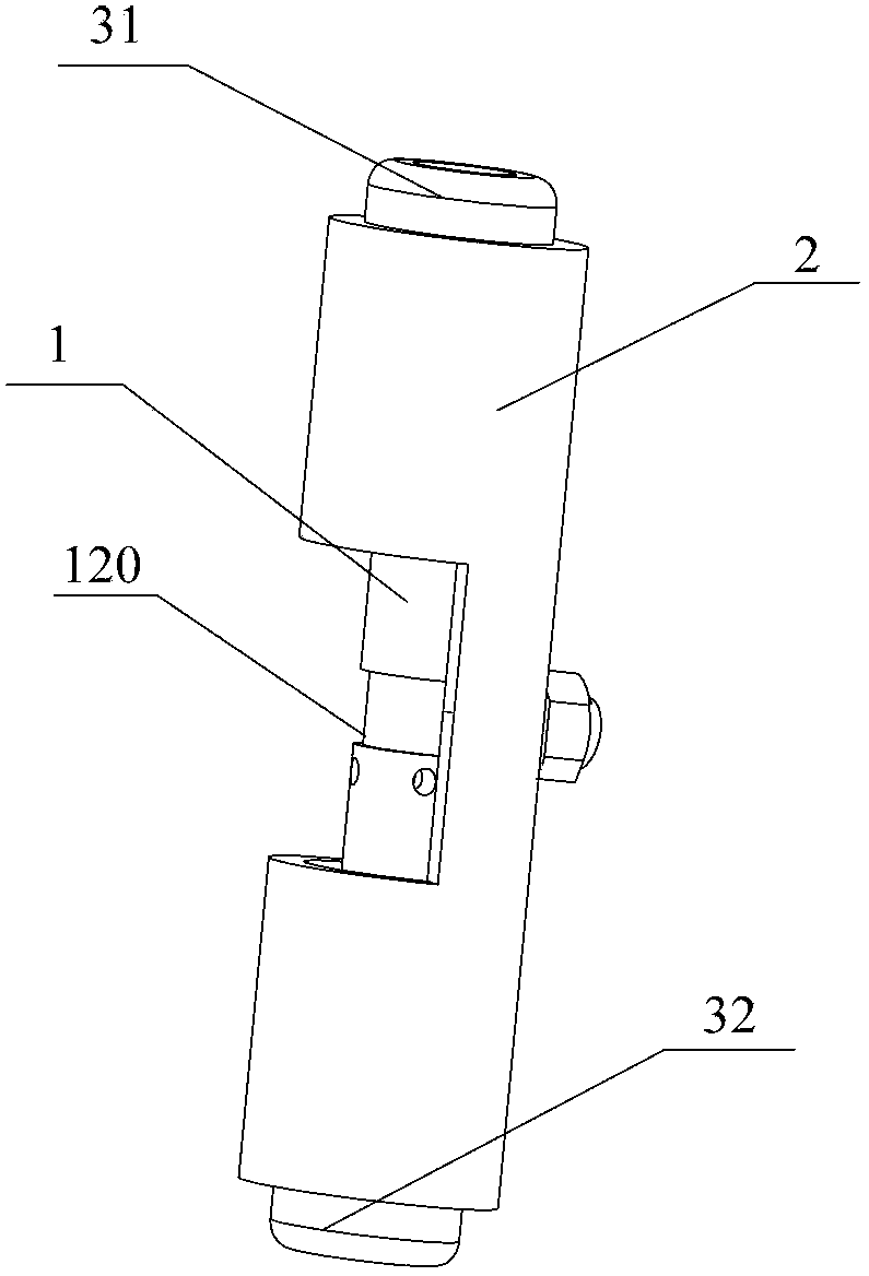
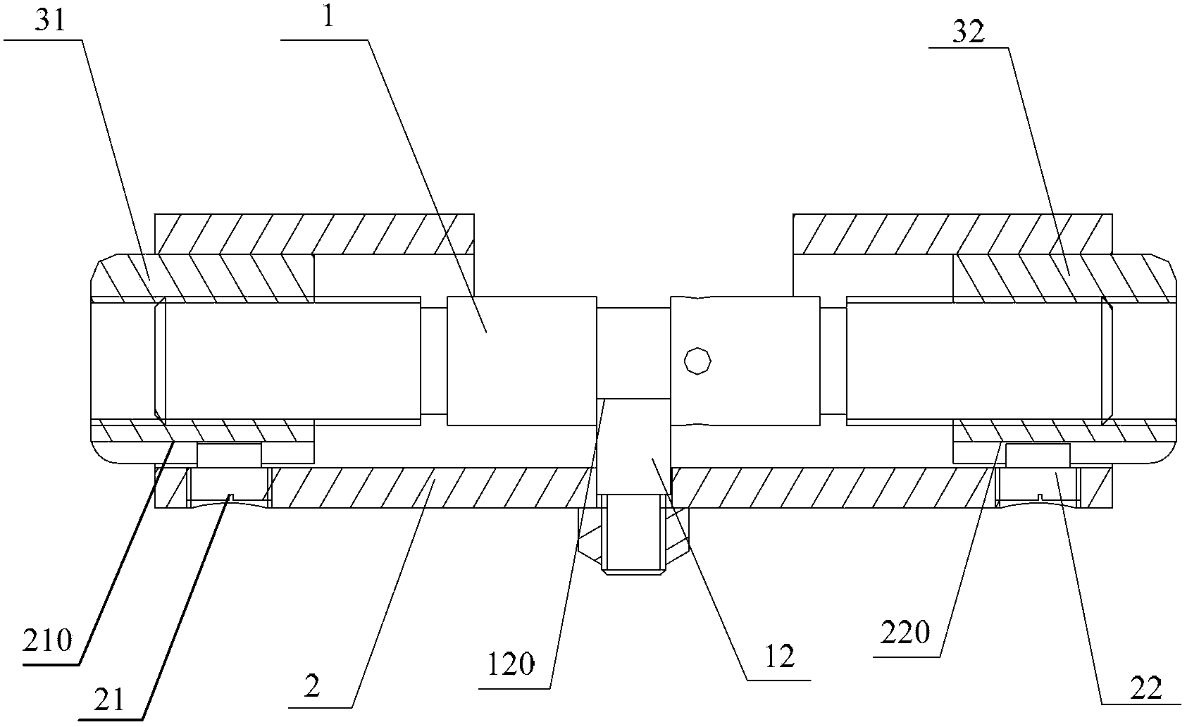
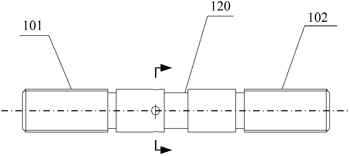
[0015] figure 1 It is a perspective view of an embodiment of the auxiliary centering tool of the present invention; figure 2 for figure 1 sectional view of image 3 for figure 1 Schematic diagram of the structure of the column rod; please refer to Figure 1-3 , this embodiment provides an auxiliary centering tool, including: a columnar rod 1 and a guide sleeve 2 sleeved outside the columnar rod, the guide sleeve 2 is connected to the columnar rod through a positioning piece 12, and the positioning piece 12 can make The cylindrical rod 1 and the guide sleeve 2 are positioned relative to each other in the axial dir...


PUM


Abstract

The invention provides an auxiliary centering fixture comprising a cylindrical bar and a guide sleeve which sleeves the cylindrical bar. The guide sleeve is connected with the cylindrical bar through a positioning member. The positioning member allows the cylindrical bar and the guide sleeve to be axially and relatively positioned and to relatively rotate in the peripheral direction. The side of each end of the cylindrical bar is provided with a thread connection portion; the thread connection portions are equal in pitch and opposite in thread direction. The thread connection portions at two ends of the cylindrical bar are connected with a first nut and a second nut in a threaded manner, respectively. The first nut and the second nut are connected with the guide sleeve respectively through a first guide member and a second guide member; the first guide member allows the first nut and the guide sleeve to be peripherally and relatively positioned and to axially and relatively move; the second guide member allows the second nut and the guide sleeve to be peripherally and relatively positioned and to axially and relatively move. A position of a middle section serving as a positioning reference can be conveniently, quickly and accurately found with the auxiliary centering fixture, and centering precision is improved.

Description

technical field [0001] The invention relates to the processing technology of mechanical parts, in particular to an auxiliary centering tool. Background technique [0002] When using machining equipment such as CNC machine tools and machining centers to process blanks, it is first necessary to align the positioning datum, that is, to adjust the processing datum of the processing equipment (the reference plane for calculating the machining amount in general index control equipment) and the rough workpiece. Datum plane alignment; Among them, the selection of the positioning datum plane of the blank directly affects the machining accuracy. [0003] Since the blank is generally a casting, the positioning error caused by using its surface as the positioning reference plane is relatively large, resulting in a decrease in the precision of the processed part; therefore, in the prior art, the middle section of the workpiece is generally used as the processing reference plane. Wherein...

Claims


Application Information

Patent Timeline
Patent Type & Authority Applications(China)
IPC IPC(8): B23Q16/00
CPCB23Q3/186
Inventor 寇玉梅杜惠锦任生德
Owner DATONG ELECTRIC LOCOMOTIVE OF NCR
Learn More