Pipe joint

a technology for pipes and joints, applied in the direction of hose connections, sleeve/socket joints, pipe joints, etc., can solve the problems of reducing workability, reducing workability, and losing the sleeve, so as to enhance the workability of the connection operation of the pipe and suppress the effect of deterioration of the sealing property

Inactive Publication Date: 2009-10-22
DAIKIN IND LTD
View PDF13 Cites 1 Cited by
  • Summary
  • Abstract
  • Description
  • Claims
  • Application Information

AI Technical Summary

Benefits of technology

[0010]According to this configuration, the sleeve that bites into the outer periphery of the pipe due to the threading of the nut to the joint body is integrated with the nut before the nut is threaded to the joint body. Therefore, as compared with the case where the sleeve is constructed as a separate body from the nut, the sleeve is prevented from being lost until the pipe is joined. Therefore, it is unnecessary to stock the sleeve as a spare. Furthermore, the work of assembling the sleeve is unnecessary when the pipe is joined to the joint body, so that the workability in the connecting operation of the pipe is enhanced.
[0011]The sleeve is separated from the nut by...

Problems solved by technology

However, the pipe joint as described above is constructed by the joint body, the nut, and the sleeve, and t...

Method used


Image

  • Pipe joint
  • Pipe joint
  • Pipe joint

Examples


first embodiment

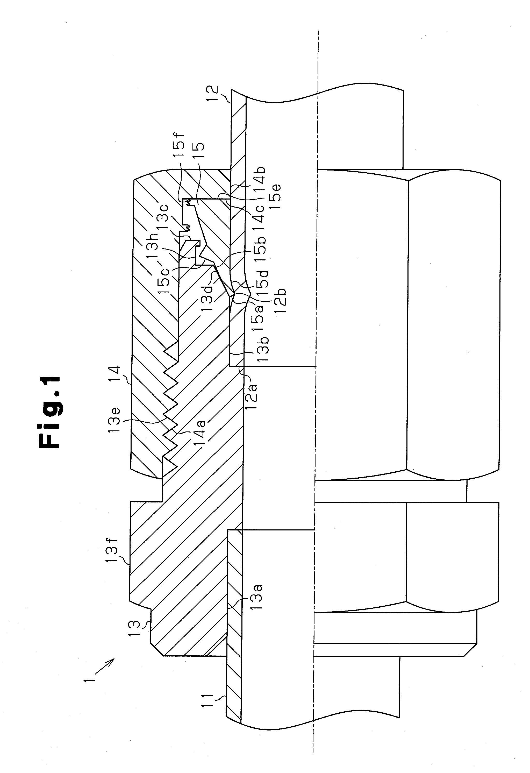
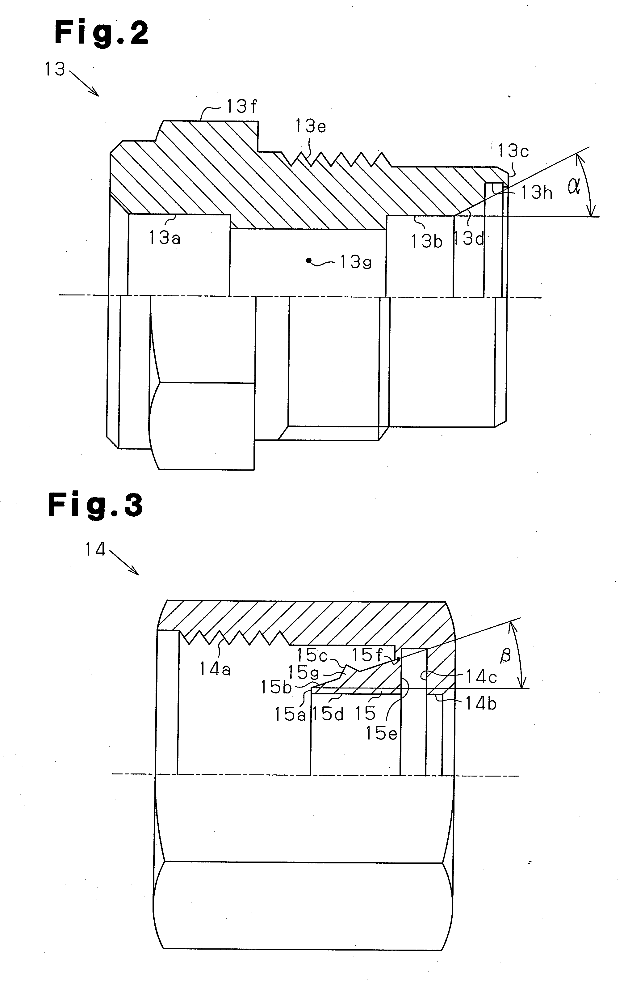
[0022]a pipe joint according to the present invention will be described with reference to FIGS. 1 to 4.

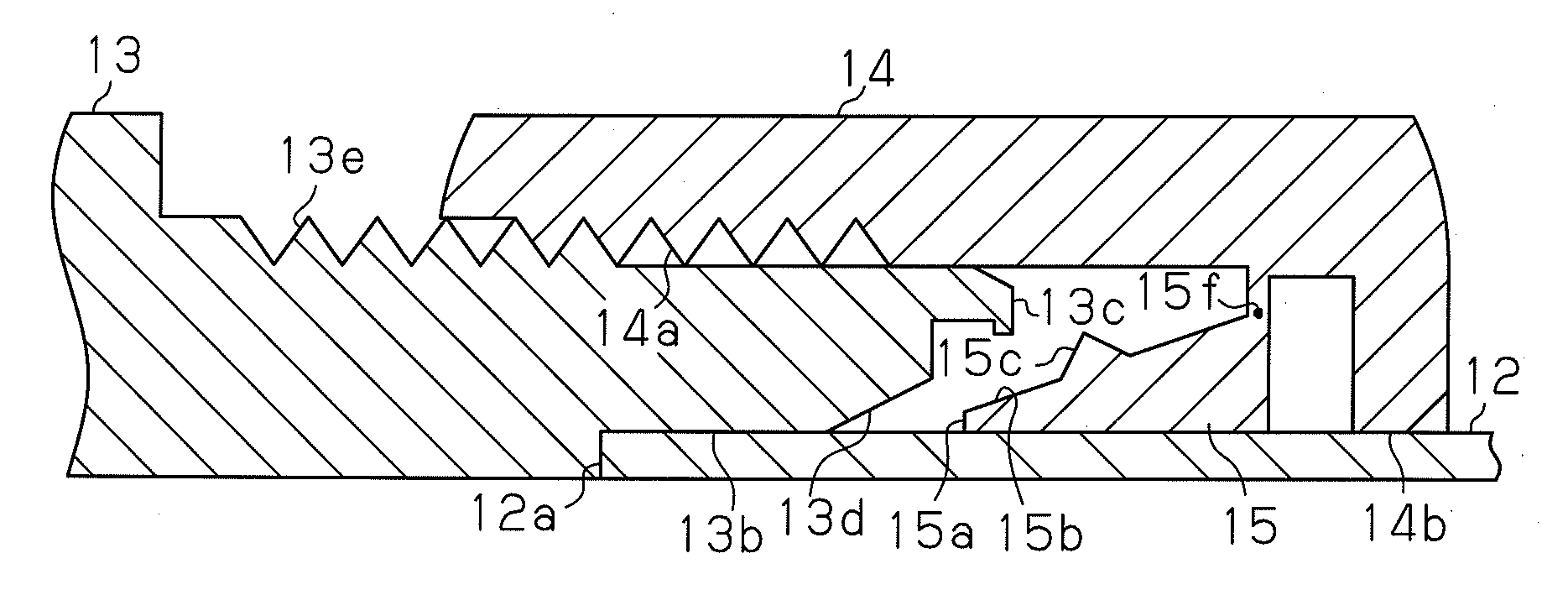
[0023]FIG. 1 is a partial cross-sectional view showing the construction of a pipe joint. The pipe joint 1 connects pipes 11 and 12, and has a joint body 13 having a cylindrical shape into which the pipes 11, 12 are inserted, a nut 14 threaded with the joint body 13, and a sleeve 15 which is interposed between the joint body 13 and the nut 14 at the pipe joining operation and has an annular shape. The pipe 11 is fixed to the joint body 13, for example, by brazing at a socket portion 13a formed at the distal portion of the joint body 13. The distal portion 12a of the pipe 12 to be connected to the joint body 13 is inserted into a joint hole 13b formed at the proximal portion of the joint body 13. The distal end portion 15a of the sleeve 15 bites into the outer peripheral surface 12b of the pipe 12 by the screwing of the nut 14 to the joint body 13, whereby the pipe 12 inserted to the...


PUM


Abstract

A pipe joint includes a sleeve that is non-movably integrated with a nut prior to the nut being threadedly coupled to a joint body. The sleeve is separated from the nut by threadedly coupling the nut to the joint body prior to contact between the sleeve and a guide surface of the joint body so as to stabilize the separation timing of the sleeve from the nut and ensure the sealing property at portions where the sleeve bites. When the nut is further threaded to the joint body, a distal end portion of the sleeve is pressed by a guide surface formed on the joint body and deformed. As a guided surface is guided by the guide surface, the distal end portion bites into an outer peripheral surface of the pipe.

Description

TECHNICAL FIELD[0001]The present invention relates to a pipe joint for joining, for example, refrigerant pipes.BACKGROUND ART[0002]A pipe joint with which a pipe is inserted into a joint portion of a joint body and then a nut is screwed to the joint body to connect the pipe to the joint portion of the joint body has been known as a pipe joint used for joining of a pipe through which fluid is made to flow into a refrigerant pipe of a refrigeration device. A flareless joint as disclosed by a prior art of Patent Document 1 has been frequently adopted as the pipe joint as described above. According to this flareless joint, when a nut is screwed into a joint body, a sleeve is interposed between the joint body and the nut, and the sleeve bites into the outer periphery of the pipe by the screwing, thereby ensuring the sealing performance between the pipe and the joint portion of the joint body.Patent Document 1: Japanese Laid-Open Patent Publication No. 2003-74768 DISCLOSURE OF THE INVENTI...

Claims


Application Information

Patent Timeline
IPC IPC(8): F16L21/04
CPCF16L19/14F16L19/10F16L19/00F16L19/08
Inventor NAKATA, HARUO
Owner DAIKIN IND LTD
Why Eureka
Try Eureka