
Method for drilling wells in close relationship using magnetic ranging while drilling

a magnetic range and well drilling technology, applied in the direction of directional drilling, borehole/well accessories, construction, etc., can solve the problems of insufficient accuracy to maintain a consistent separation distance, essentially impossible to meet spacing requirements using conventional surveying techniques, and generally too viscous oil to be produced from a conventional well

Inactive Publication Date: 2009-10-22
SCHLUMBERGER TECH CORP
View PDF41 Cites 65 Cited by
  • Summary
  • Abstract
  • Description
  • Claims
  • Application Information

AI Technical Summary

Benefits of technology

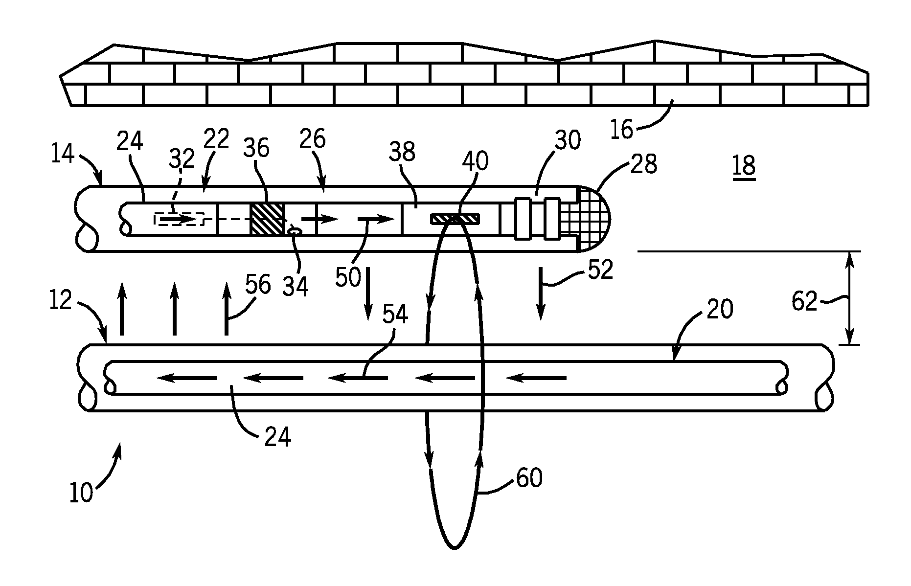
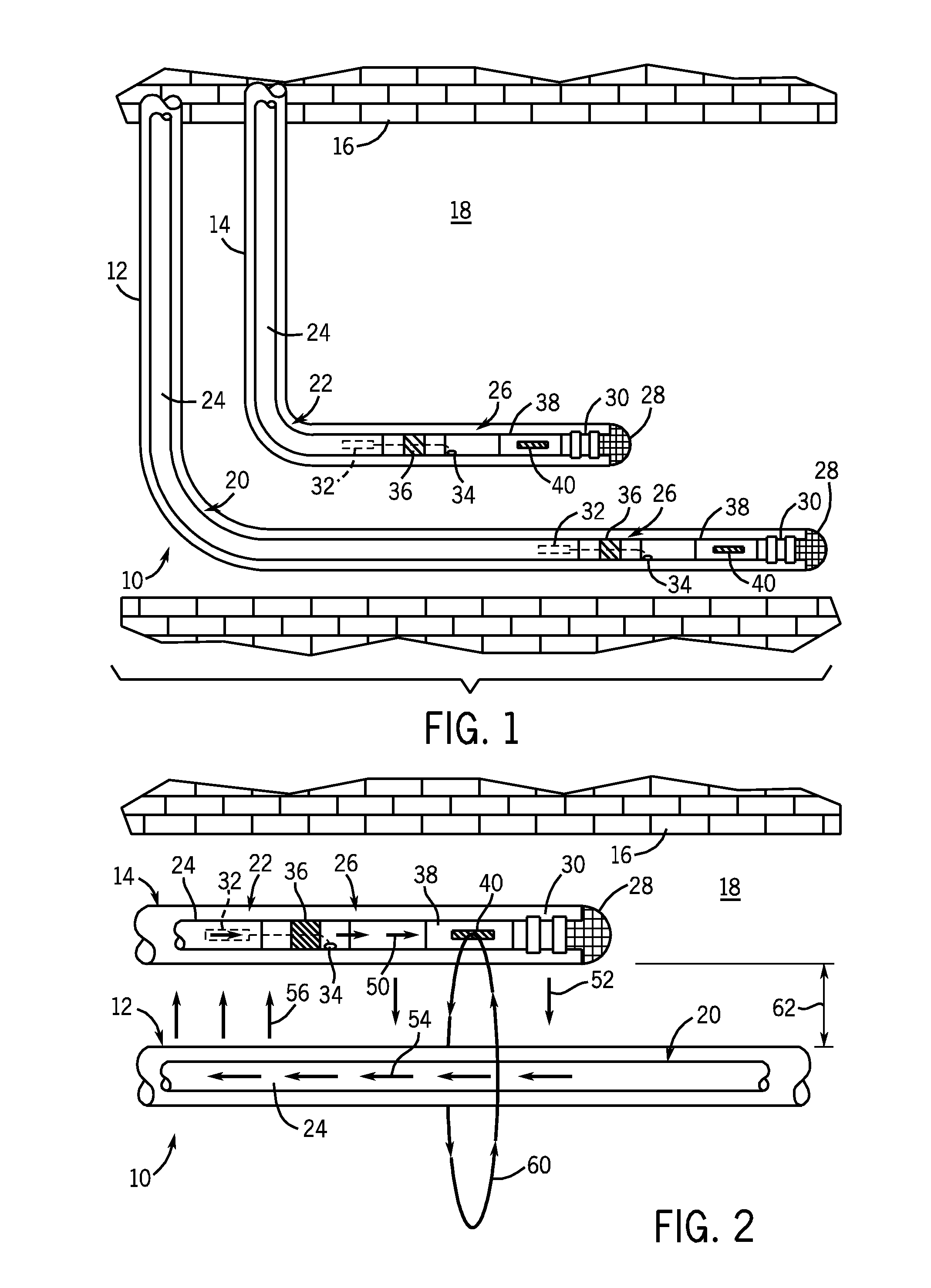
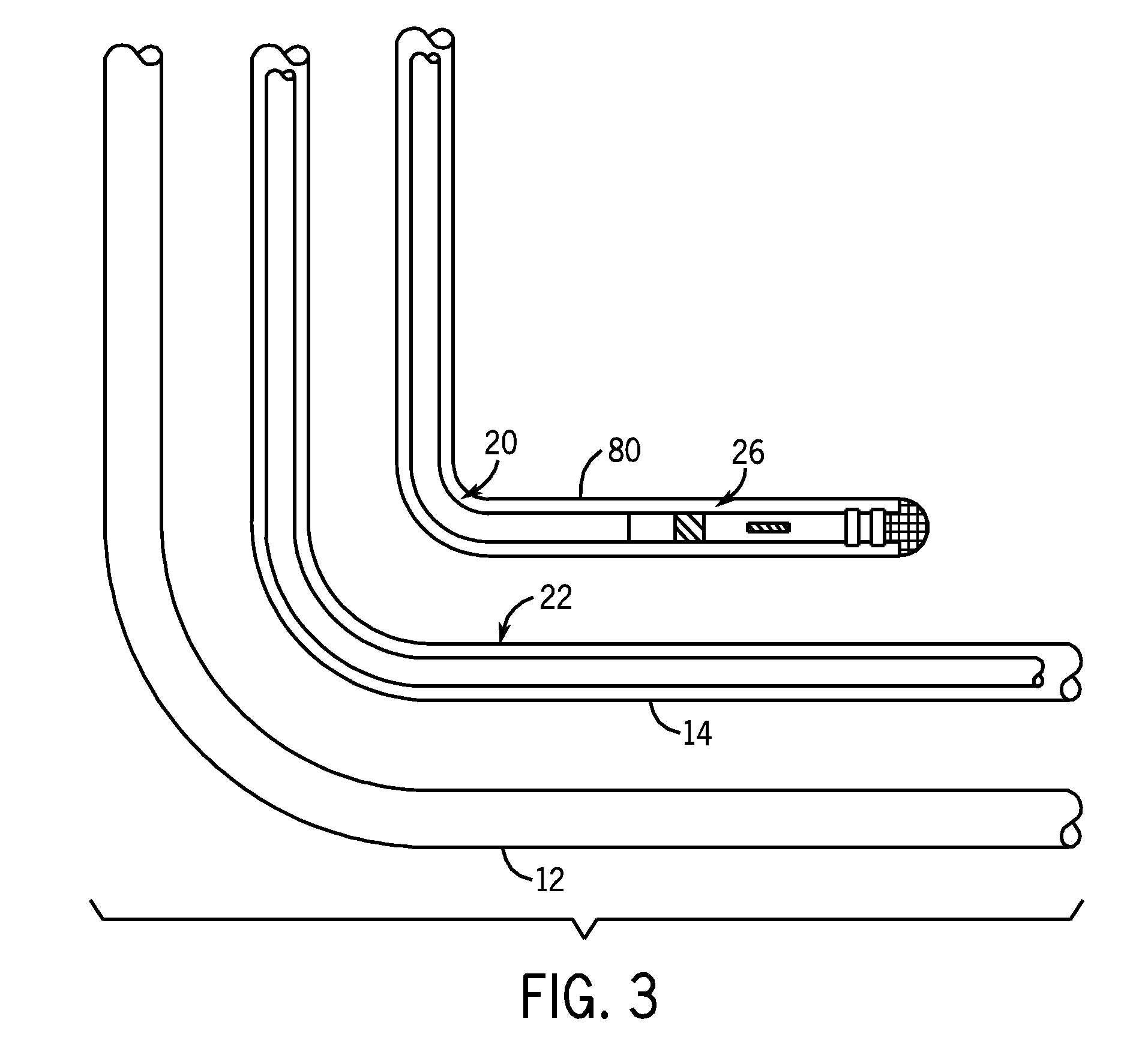
The patent describes a method of drilling a well by using a drill string in a primary well as a target for magnetic ranging while drilling a secondary well. This allows the secondary well to be positioned with a specific orientation relative to the drill string. The technical effect of this method is to improve the accuracy and efficiency of drilling wells.

Problems solved by technology

Indeed, heavy oil is generally too viscous in its natural state to be produced from a conventional well.
When wells are drilled close to one another, there are typically spacing requirements that are essentially impossible to meet using conventional surveying techniques.
Conventional measurement while drilling (MWD) survey data, which may only include inclination and azimuth data, does not provide sufficient accuracy to maintain a consistent separation distance between the injector well and the producer well.
However, when the wells are horizontal, these conventional magnetic ranging techniques require a wireline tractor to push the wireline tool down the length of the first horizontal well as the second well is being drilled.
This can be an expensive procedure in a typical cased-hole tractor operation.
Further, such a procedure may be even more difficult, expensive, and risky for an openhole tractor operation.

Method used


Image

  • Method for drilling wells in close relationship using magnetic ranging while drilling
  • Method for drilling wells in close relationship using magnetic ranging while drilling
  • Method for drilling wells in close relationship using magnetic ranging while drilling

Examples


Embodiment Construction

[0013]One or more specific embodiments of the present invention are described below. In an effort to provide a concise description of these embodiments, not all features of an actual implementation are described in the specification. It should be appreciated that in the development of any such actual implementation, as in any engineering or design project, numerous implementation-specific decisions must be made to achieve the developers' specific goals, such as compliance with system-related and business-related constraints, which may vary from one implementation to another. Moreover, it should be appreciated that such a development effort might be complex and time consuming, but would nevertheless be a routine undertaking of design, fabrication, and manufacture for those of ordinary skill having the benefit of this disclosure.

[0014]In well drilling operations, it may be desirable to place wells close together or in specific orientations relative to one another. Indeed, in SAGD oper...


PUM


Abstract

Methods for drilling wells using magnetic ranging while drilling to position the wells with respect to one another are provided. In accordance with one embodiment, a method of drilling a well includes leaving a drill string in position within a primary well, and drilling a secondary well using the drill string as a target for magnetic ranging while drilling such that the secondary well is positioned with a specified orientation relative to the drill string.

Description

FIELD OF THE INVENTION[0001]The present invention relates generally to well drilling operations and, more particularly, to well drilling operations using magnetic ranging to drill wells in specified orientations with respect one another, wherein the wells may include wells to be completed open hole and / or wells to be completed with equipment disposed therein and hindering access to the wellbore.BACKGROUND OF THE INVENTION[0002]It is often desirable to position wells close together. For example, in certain oilfield applications, drilling wells close together may facilitate extraction of heavy oil. Indeed, heavy oil is generally too viscous in its natural state to be produced from a conventional well. Accordingly, to produce heavy oil, multiple wells, such as a pair of Steam Assisted Gravity Drainage (SAGD) wells, may be employed. A SAGD well pair typically includes two substantially parallel horizontal wells that are positioned relatively close together in a stacked orientation, and ...

Claims


Application Information

Patent Timeline
Patent Type & Authority Applications(United States)
IPC IPC(8): E21B7/04
CPCE21B43/305E21B47/0905E21B47/02216E21B47/0228E21B47/092
Inventor MORLEY, JAN S.CLARK, BRIAN
Owner SCHLUMBERGER TECH CORP
Learn More