
External resonator variable wavelength laser and its packaging method

a variable wavelength, laser technology, applied in semiconductor lasers, laser details, electrical devices, etc., can solve the problems of large frequency accuracy degradation, difficult to further reduce reflectance, and difficult to check the frequency of one transmission band of fp etalon, etc., to achieve high wavelength accuracy

Inactive Publication Date: 2009-10-15
NEC CORP
View PDF5 Cites 12 Cited by
  • Summary
  • Abstract
  • Description
  • Claims
  • Application Information

AI Technical Summary

Benefits of technology

[0034]According to the external cavity wavelength tunable laser of the present invention, there can be provided a wavelength tunable laser with high wavelength accuracy which can suppress a shift from the transmission characteristic peak of the wavelength selection filter due to intracavity etalons.
[0035]In addition, according to the external cavity wavelength tunable laser of the present invention, the transmission band of the wavelength selection filter can be matched with an ITU grid more easily than by the conventional mounting method, thereby mounting the wavelength selection filter in a short period of time.

Problems solved by technology

It is technically difficult to further reduce the reflectance.
This is because, since a reduction in the reflectance of the cavity side end face of the semiconductor optical amplifier is not sufficient, even though the reflectance of the end face is reduced, intracavity etalons are respectively formed between the two end faces of the semiconductor optical amplifier and between an end face of the semiconductor optical amplifier and an external reflection mirror.
If no external cavity is formed, since laser oscillation a does not occur, it is difficult to check the frequencies of one transmission band of the FP etalon.
In consideration of a wide frequency range of 4 THz or more, such differences will lead to a great deterioration in frequency accuracy.
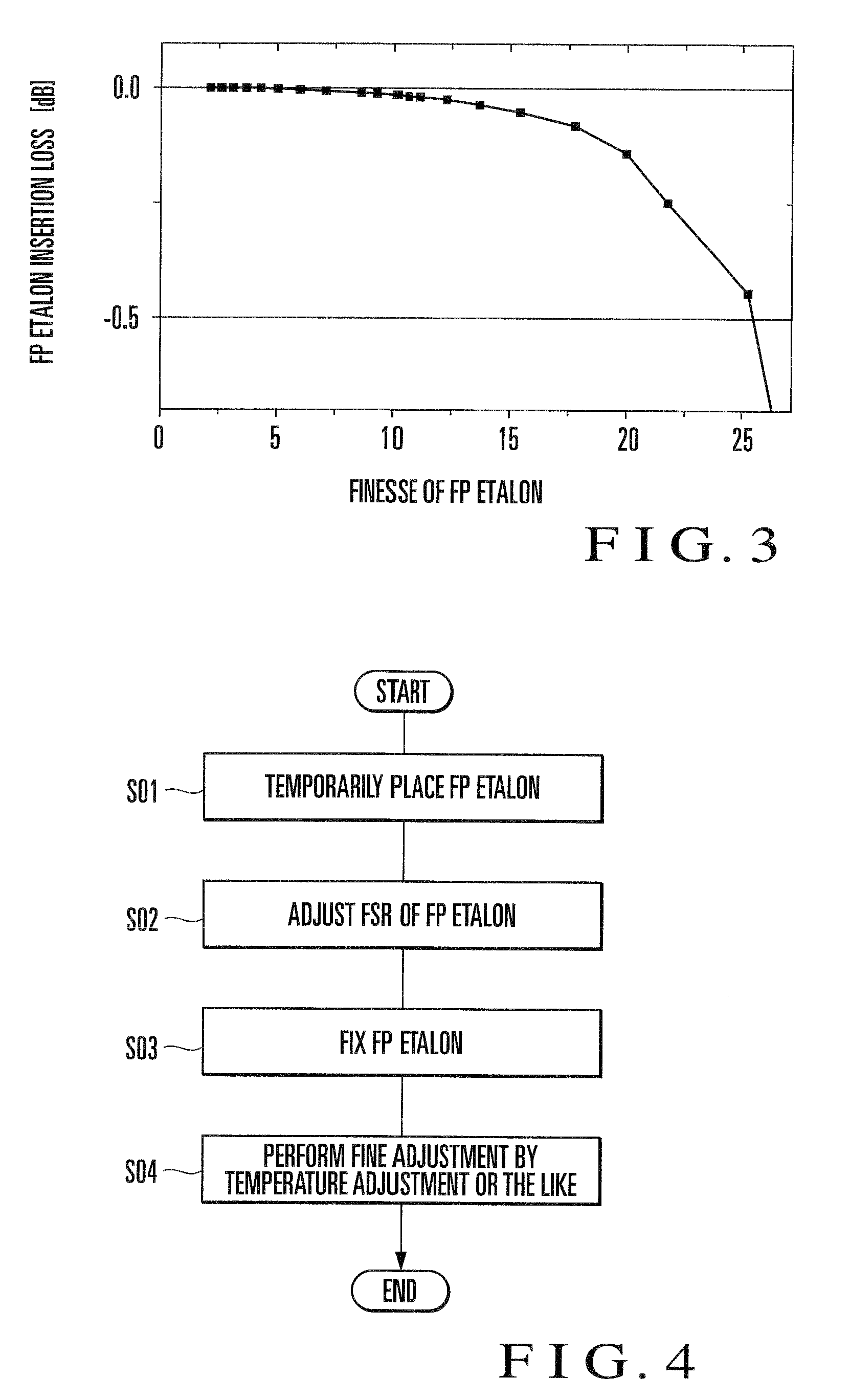
As described above, the conventional etalon mounting technique requires more complicated operation and a longer period of time because of the shift between the ITU grid interval and the FSR of the FP etalon.
Furthermore, since it is impossible to sufficiently check wavelength accuracy with a spectrum analyzer, the wavelength accuracy is generally about 1 GHz in a wide frequency range of 4 THz or more in real term.

Method used


Image

  • External resonator variable wavelength laser and its packaging method
  • External resonator variable wavelength laser and its packaging method
  • External resonator variable wavelength laser and its packaging method

Examples


first embodiment

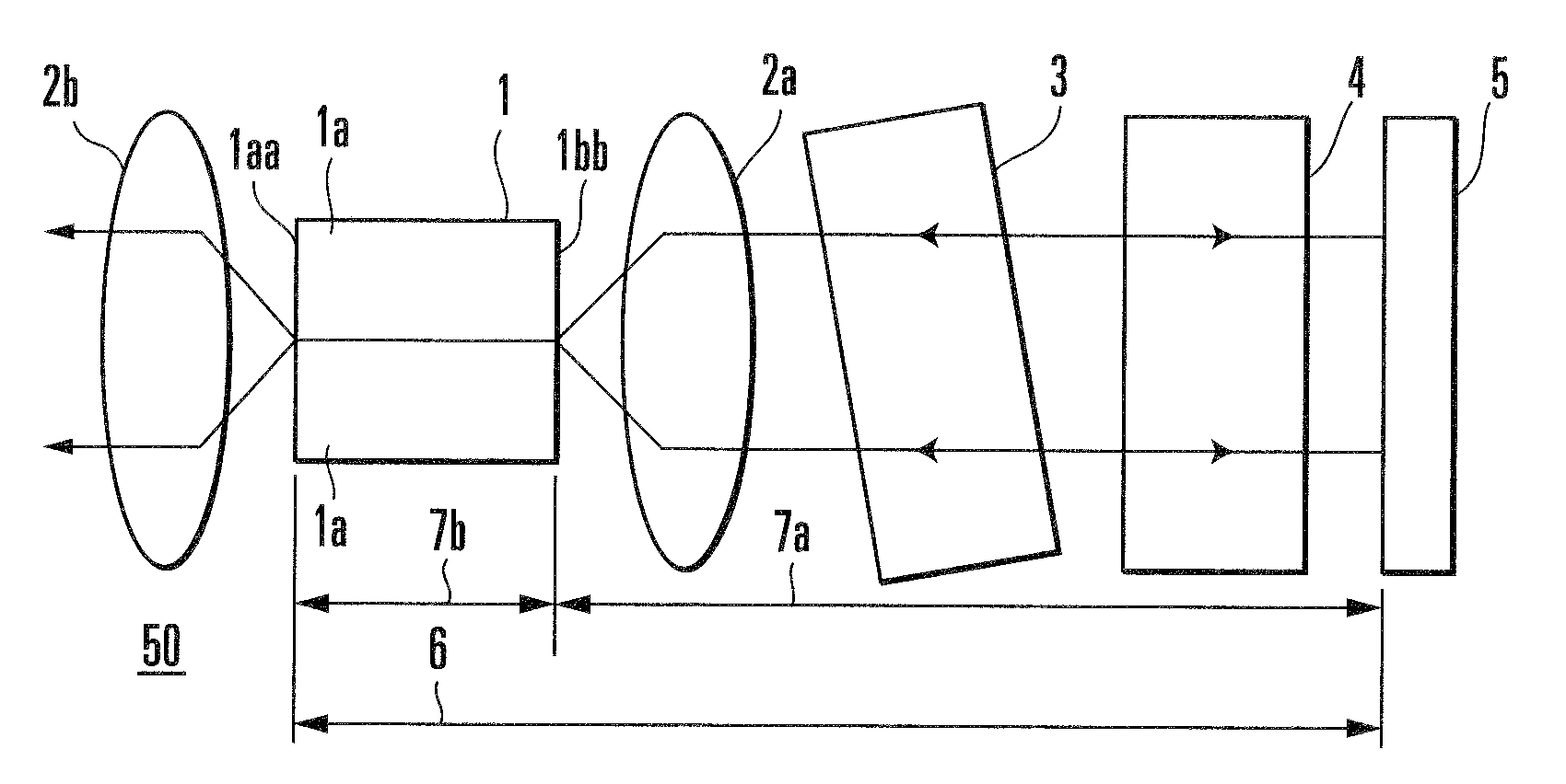
[0053]An external cavity wavelength tunable laser according to this embodiment is an external cavity wavelength tunable laser including at least a semiconductor optical amplifier, a reflection means which is placed to face one end face of the semiconductor optical amplifier to form an external cavity, a wavelength selection filter which is placed between the semiconductor optical amplifier and the reflection means and has a periodic transmission characteristic with respect to frequency, and a wavelength tunable filter which selectively transmits light with an arbitrary frequency of the plurality of frequencies selected by the wavelength selection filter.

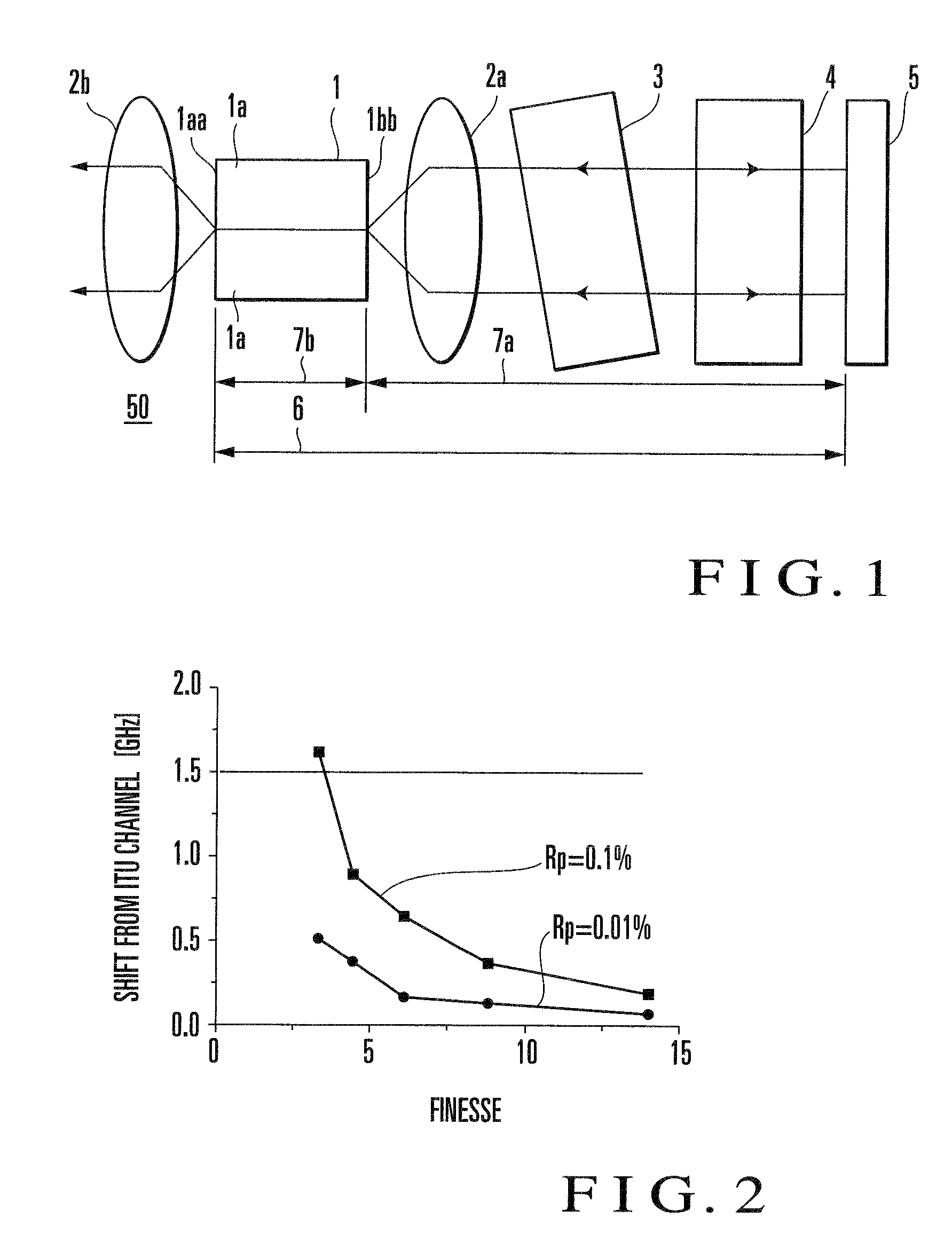
[0054]The external cavity wavelength tunable laser according to this embodiment is characterized in that (a) the reflectance of one end face of the external cavity of the semiconductor optical amplifier is 0.1% at most, and the finesse value obtained by dividing the period of the transmission characteristic of the wavelength selectio...

second embodiment

[0109]An external cavity wavelength tunable laser according to this embodiment has the following three characteristic features, in addition to those of the external cavity wavelength tunable laser according to the first embodiment, namely (a) an external cavity incorporates a phase adjustment mechanism, (b) an FP etalon is used as a wavelength selection filter and placed such that the angle defined by a normal line on the etalon surface and the optical axis of light exiting from the semiconductor optical amplifier falls in the range of 0° or more and 2° of less, and (c) a wavelength tunable filter and a reflection means are integrally formed by using a wavelength tunable mirror.

[0110]A specific arrangement of the external cavity wavelength tunable laser according to this embodiment will be described below.

[0111]The basic arrangement of the external cavity wavelength tunable laser according to this embodiment comprises a semiconductor optical amplifier, collimating lenses, a waveleng...

third embodiment

[0124]An external cavity wavelength tunable laser according to this embodiment has the following two characteristic features, in addition to those of the external cavity wavelength tunable laser according to the first embodiment, namely (a) an external cavity incorporates a phase adjustment mechanism and (b) an FP etalon is used as a wavelength selection filter and placed such that the angle defined by a normal line on the etalon surface and the optical axis of light exiting from the semiconductor amplifier falls in the range of 0° or more and 2° of less.

[0125]The external cavity wavelength tunable laser according to this embodiment will be described with reference to FIG. 10.

[0126]In this external cavity wavelength tunable laser, a semiconductor optical amplifier 1 has a length of 900 μm, the reflectance of an exit side end face 1aa is set to 12% so as to reduce a laser threshold and stabilize operation, and the reflectance of a low-reflectance end face is set to 0.01%. As a wavele...


PUM


Abstract

The reflectance of a semiconductor optical amplifier (1) on the side where an external cavity is formed is 0.1% at most. The finesse value obtained by dividing the period of the transmission characteristic of the wavelength selection filter (3) by the half value width of the transmission characteristic is 4 or more and 25 or less. Even when the reflectance of a cavity side end face (1bb) of the semiconductor optical amplifier (1) is about 0.1%, a wavelength accuracy of ±1.5 GHz can be achieved by setting the finesse to 4 or more. In addition, a wavelength accuracy of about ±0.5 GHz can be achieved by setting the finesse to 8 or more. In order to suppress insertion loss, it is preferable to set the finesse of the FP etalon to 25 or less. This makes it possible to implement an external cavity wavelength tunable laser with high wavelength accuracy.

Description

TECHNICAL FIELD[0001]The present invention relates to an external cavity wavelength tunable laser having high wavelength accuracy and its implementation method.BACKGROUND ART[0002]Recently, with the rapid proliferation of the Internet, there has been a demand for a further increase in communication traffic. Under the circumstance, the transmission rate per unit channel in a system has increased as well as the number of channels based on wavelength division multiplexing (WDM).[0003]In such a wavelength division multiplexing system, importance is placed on a laser which has high single mode stability at a specific frequency (to be referred to as an “ITU grid” hereinafter) standardized by ITU (International Telecommunications Union). The ITU grid interval tends to decrease from 100 GHz to 50 GHz. As the frequency interval decreases in this manner, it is necessary to keep the laser oscillation frequency constant with high accuracy. In general, the laser needs to have an optical power ch...

Claims


Application Information

Patent Timeline
Patent Type & Authority Applications(United States)
IPC IPC(8): H01S3/10H01S3/00
CPCH01S5/028H01S5/0287H01S5/142H01S5/0687H01S5/141H01S5/0625
Inventor MIZUTANI, KENJIDE MERLI, JANKUDO, KOJISATO, KENJISUDO, SHINYA
Owner NEC CORP
Learn More