Method for reducing video image latency

a video image and latency reduction technology, applied in the field of latency reduction, can solve the problems of old image being displayed, generally rate-limiting activity in the rear buffer, and the image being presently displayed, etc., and achieve the effect of reducing image latency

Active Publication Date: 2009-10-15
MERCURY MISSION SYST LLC
View PDF6 Cites 4 Cited by
  • Summary
  • Abstract
  • Description
  • Claims
  • Application Information

AI Technical Summary

Benefits of technology

[0012]Exemplary embodiments provide a method for reducing image latency in a video display system that uses a stroke video frame technique in which a video image is displayed for a stroke video frame period.
[0018]By repeating the displaying and rotating steps, the image latency is reduced.
[0022]Obvious modifications are expected to fall within the scope of the claims, including increasing the number of memory buffers used in the video display system or staggering the order of the time periods or the ordering of the buffers. In addition to the above stated advantages, other advantages will be better understood from the following description of the drawings and detailed description of the preferred embodiment(s).

Problems solved by technology

An easily recognized problem of the double buffered system is that the image being presently displayed, that is, image M, is “old,” because it was assembled during frame time M−1 and not during frame time M. It will also be recognized that it is the activity in the rear buffer that is generally rate-limiting.
It is also known to provide more than two buffers, however this can increase latency to greater than one frame time in the absence of artificially imposed constraints.

Method used


Image

  • Method for reducing video image latency
  • Method for reducing video image latency
  • Method for reducing video image latency

Examples


embodiment 1

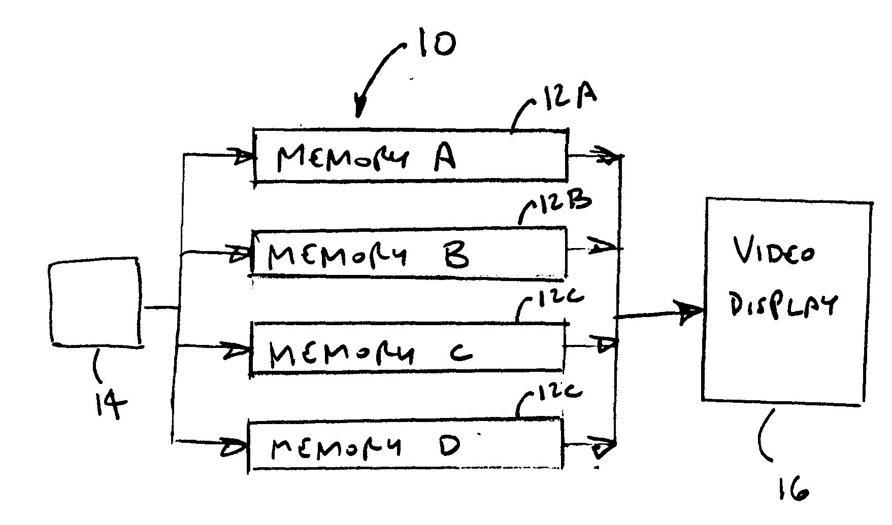
[0033]FIG. 1 schematically illustrates a first embodiment 10 where four raster memory buffers 12, sub-designated as A through D, are provided. Each raster memory buffer 12 is divided into four quarters for receiving stroke video frames in one-quarter portions. Each raster memory buffer 12 is adapted to be in communication with an input source 14, from which input data comprising the stroke video frames are received, that is, each buffer may be in a receiving condition. Each raster memory buffer 12 is also adapted to be communicated with a display device 16, on which the data are visually presented, that is, each buffer may also be in a display condition. In this embodiment, the raster memory buffers 12 are rotated so that each becomes the “front” or display buffer once in each stroke video frame. In a 60 Hz system, for example, as is conventional in the United States, where a stroke video frame is 16.67 msec in duration, the raster memory buffers 12 will be sequentially rotated ever...

embodiment 2

[0043]FIG. 3 schematically illustrates a five-memory-buffer video display system 110. In this setup, five raster memory buffers 112, sub-designated as A through E, are provided. Each raster memory buffer 112 is divided into four quarters for receiving stroke video frames in one-quarter portions. Each raster memory buffer 112 is in communication with an input source 14, from which input data comprising the stroke video frames are received. Each raster memory buffer 112 is also communicated with a display device 16, on which the data are visually presented. In this embodiment, the raster memory buffers 112 are rotated so that each becomes the “front” or display buffer once in each stroke video frame. In a 60 Hz system, for example, as is conventional in the United States, where a stroke video frame is 16.67 msec in duration, the raster memory buffers 112 will be sequentially rotated every 4.167 msec, that is, every 0.25 stroke video frame. In a 50 Hz system, as would be conventional i...

embodiment 3

[0056]A third embodiment is achieved using the same four-memory-buffer setup as shown in FIG. 1. In this embodiment, as in the first embodiment, four memory buffers, designated as A through D, are provided.

[0057]Referring to FIG. 5, during a first rmb time period T1 (0 to 0.25 svf), image data in raster memory buffer D are displayed. The displayed data are the last 50% of an image designated as Stroke Video Frame (“SVF”) 0. The first two quarters of raster memory buffer D will be empty, so the displayed image for those portions will be effectively a black screen, although the time on the screen will be sufficiently short that this will not be visually perceptible. Simultaneously (at least within rmb time period T1), a first quarter portion of SVF 1 is being written to raster memory buffers A, B and C. In one variation of this embodiment, raster memory buffers B and C are erased before any writing is made to them. In another embodiment, raster memory buffer C is only erased during ti...


PUM


Abstract

Image latency is reduced in a video display system where an image is displayed for a stroke video frame period. The system has a display device and a plurality of memory buffers, each of which is adapted to receive image data (in a receiving condition) or to display data to the display device (in a display condition). The stroke video frame period is divided into at least two time periods and the number of memory buffers provided is at least the number of time periods per stroke video frame period. One of the memory buffers is in the display condition for a first time period, with the remaining memory buffers in the receiving condition. At the end of the time period, the memory buffers are rotated so that the displayed memory buffer moves to the receiving condition and one of the receiving buffers moves into the display condition.

Description

CROSS-REFERENCE TO RELATED APPLICATIONS[0001]This application is a non-provisional patent application and claims priority to co-pending application No. 61 / 045,154 filed Apr. 15, 2008.TECHNICAL FIELD[0002]Exemplary embodiments relate generally to a method for reducing latency particularly with regard to converting a “stroke” generated video image into a “raster” type display.BACKGROUND OF THE ART[0003]“Stroke” type video display systems, as typically used in cathode ray tube (CRT) video display units in the 1960s and 1970s, drew their images on a “real time” basis to the screen. That is to say, as soon as a graphic display element is defined, it is “stroked” directly to the phosphor face of the CRT, using x-y deflection of an electron beam and “z” video modulation. Such a stroke system has no refresh memory, so the image on the screen is updated and refreshed at the scan rate of the screen, which is typically 60 Hz, or 16.67 msec. While such stroke systems had other problems associat...

Claims


Application Information

Patent Timeline
Patent Type & Authority Applications(United States)
IPC IPC(8): G09G5/36
CPCG06F3/1475G09G2380/12G09G2320/0252G09G5/399
Inventor DUNN, WILLIAM
Owner MERCURY MISSION SYST LLC
Why Eureka
Try Eureka