
Photovoltaic heat-weldable thermoplastic roofing membrane

a thermoplastic roofing and thermoplastic technology, applied in the direction of heat collector mounting/support, photovoltaic support, pv power plants, etc., can solve the problems of power transmission infrastructure investment and the reduction of the photoelectric conversion efficiency of the cell

Inactive Publication Date: 2009-10-15
BUILDING MATERIALS INVESTMENT
View PDF8 Cites 27 Cited by
  • Summary
  • Abstract
  • Description
  • Claims
  • Application Information

AI Technical Summary

Benefits of technology

[0012]This disclosure pertains to the fusing of photovoltaic modules or cells to a heat-weldable thermoplastic roofing membrane, and related methods of manufacturing and installation for such a roofing membrane product. The resulting membrane may be used as the back sheet for sealing the back surface of photovoltaic cells / modules. According to one aspect, this disclosure provides the attachment of a photovoltaic module to a roof membrane directly. According to another aspect, however, a fluorinated vinyl polymer film, such as polyvinyl fluoride (PVF) or polyvinylidene fluoride (PVDF), is laminated to the top surface of the heat-weldable thermoplastic roofing membrane prior to the affixing of the solar modules. Constructing a photovoltaic module on a heat-weldable thermoplastic underlying membrane in accordance with the principles disclosed herein provides several advantages over conventional construction techniques and materials, and these advantages are discussed in greater detail below. As used herein, the term “heat-weld” and its variants refers to the heat-based or molten fusing of like or substantially similar materials to bond the materials together in a manner more permanent than merely adhering the materials together. The process would involve the heating of the materials at the point of the bond to a molten or partially liquefied state such that the materials fuse to one another at the heated bond point(s) with or without the use of a third material, such as a flux material, used to promote the fusing.

Problems solved by technology

They have a disadvantage due to their distance from areas of electricity consumption, and require power transmission infrastructure investment.
One challenge facing the industry is the specific type of photovoltaic cells employed.
However, a key reason why a glass plate is used at the outermost surface side is that the solar cell module is made to excel in weatherability and scratch resistance so that the photoelectric conversion efficiency of the cell is not reduced due to a reduction in the light transmittance of the surface-covering material when the surface-covering material is deteriorated.

Method used


Image

  • Photovoltaic heat-weldable thermoplastic roofing membrane
  • Photovoltaic heat-weldable thermoplastic roofing membrane
  • Photovoltaic heat-weldable thermoplastic roofing membrane

Examples


Embodiment Construction

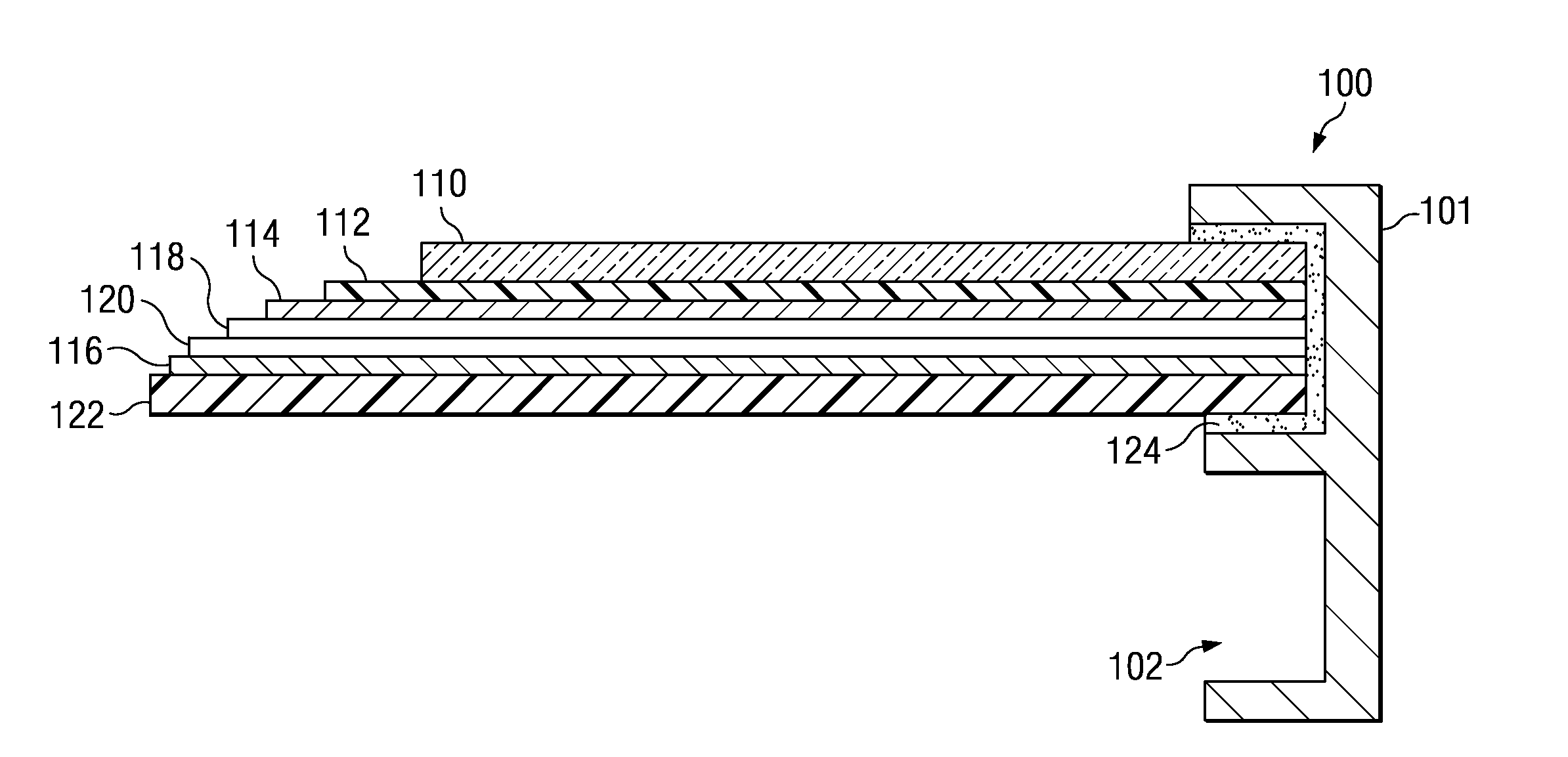
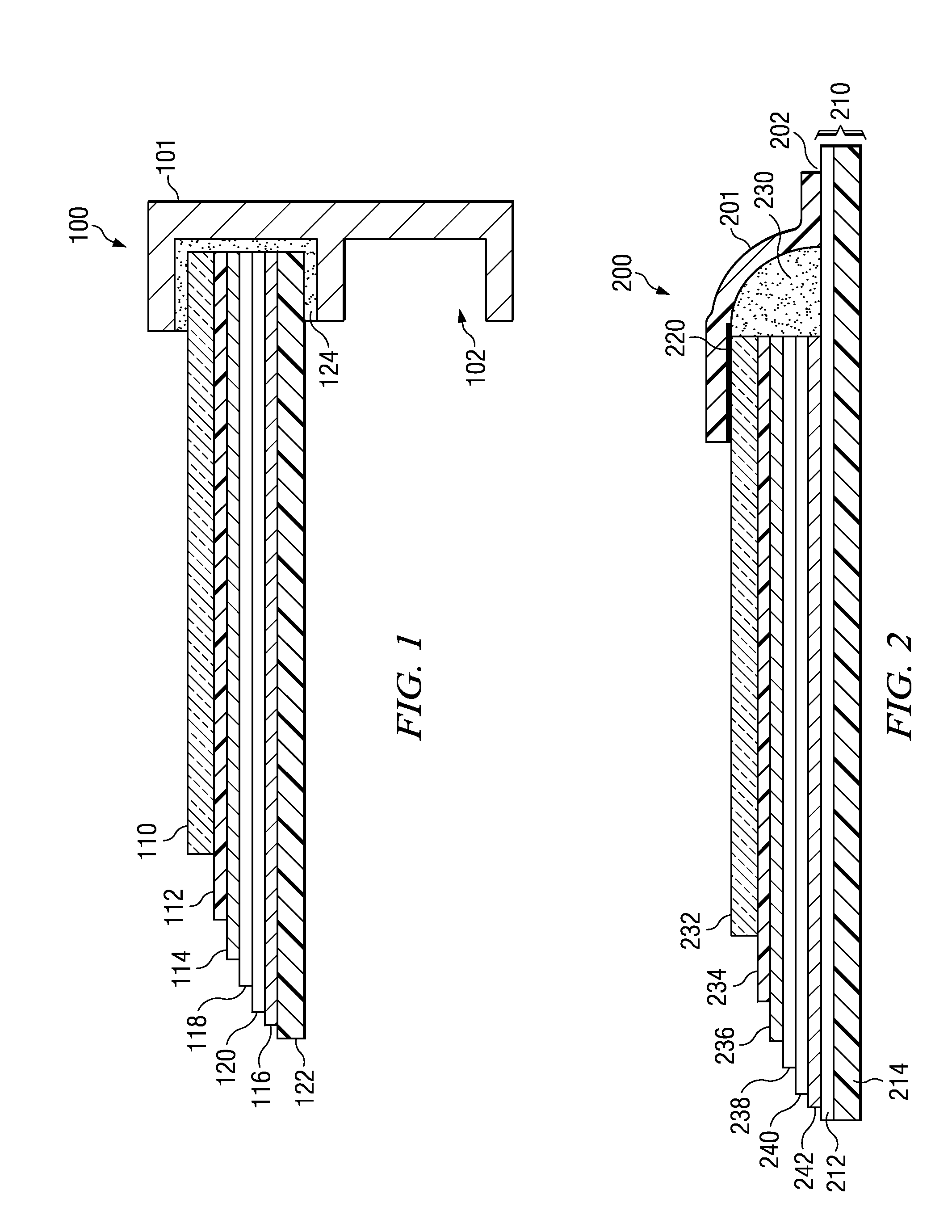
[0018]FIG. 1 is a drawing illustrating a partial side cross-sectional view of the construction of a conventional photovoltaic module 100 for a generic silicon type solar cell. A rack to hold the module 100 includes a metal frame 101 for both protection of the edge of the photovoltaic module 100 and as a means of mounting the cell to the structure. More specifically, the slot 102 of the metal frame 101 provides a means for mounting the photovoltaic module 100, and the metal frame 101 provides mechanical protection for the edge of various layers of the photovoltaic module 100. A glass superstrate 110 is the top layer of the photovoltaic module 100, which necessarily results in the module 100 being a rigid module 100. Such rigid modules 100 use racks, as mentioned above, to seal the edges of the module 100 as well as to affix the modules 100 to the structure. Unfortunately, such racks used with rigid systems add complexity and cost to the manufacturing and installation process.

[0019]Al...


PUM

PropertyMeasurementUnit
timeaaaaaaaaaa
transparentaaaaaaaaaa
perimeteraaaaaaaaaa

Abstract

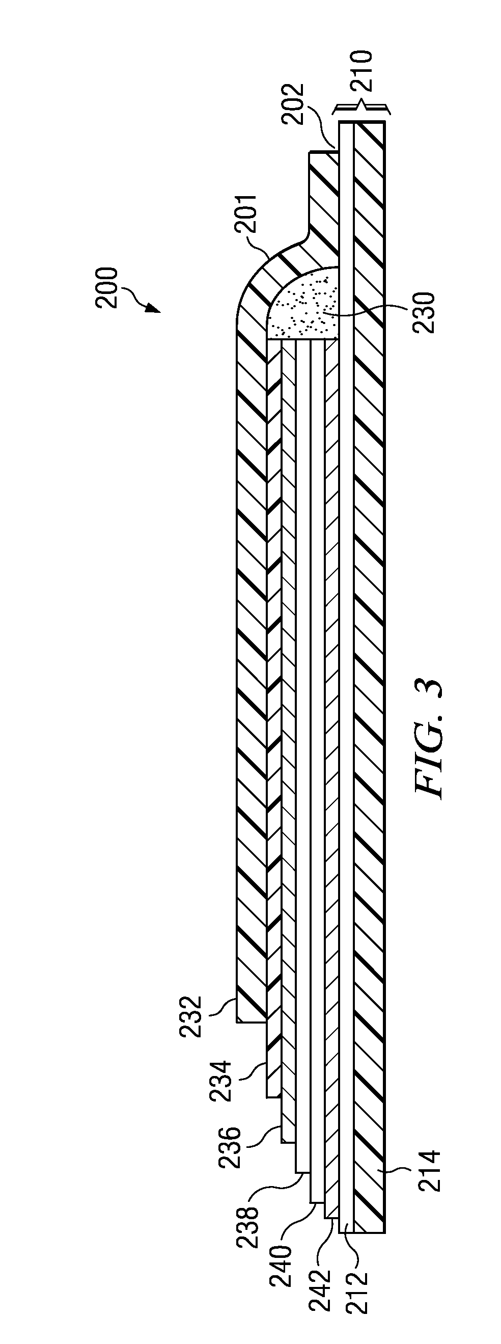
Disclosed herein is the fusing of photovoltaic modules or cells to a heat-weldable thermoplastic roofing membrane, and related methods of manufacturing of the same. The resulting membrane may be used as the back sheet for sealing the back surface of photovoltaic cells / modules. In one embodiment, such a photovoltaic roofing structure may comprise a photovoltaic module with an active layer and electrodes, a transparent superstrate, and a thermoplastic olefin membrane. The transparent superstrate may be positioned on top of the photovoltaic module. Also included may be an underlying membrane comprising heat-weldable thermoplastic material positioned beneath the photovoltaic module. In addition, a frame comprised of the same heat-weldable thermoplastic material as the underlying membrane may be located on a perimeter of the superstrate and the photovoltaic module. The frame is then heat-welded to the underlying membrane around the perimeter of the photovoltaic module. Also disclosed herein are related methods of manufacturing such a photovoltaic roofing structure.

Description

CROSS REFERENCE TO RELATED APPLICATIONS[0001]This patent application relates and claims priority to provisional patent application 61 / 044,134, filed Apr. 11, 2008, which is herein incorporated by reference for all purposes.TECHNICAL FIELD[0002]This invention relates generally to photovoltaic roofing products, and more particularly to the use of a heat-weldable thermoplastic roofing membrane as the backsheet for photovoltaic (PV) modules.BACKGROUND[0003]Solar energy has received increasing attention as a renewable, non-polluting energy source to produce electricity as an alternative to other non-renewable energy resources, such as coal or oil, which generate pollution. Given the increase in the price of non-renewable resources such as oil, it has become even more advantageous for companies and individuals to look to solar energy as a cost saving alternative.[0004]In general, photovoltaic power generation systems involve photovoltaic power generation panels with solar cells converting...

Claims


Application Information

Patent Timeline
Patent Type & Authority Applications(United States)
IPC IPC(8): H01L31/048C09J5/00
CPCH02S20/23Y02B10/12F24S2025/601Y02E10/50Y02B10/10
Inventor TAYLOR, THOMAS J.
Owner BUILDING MATERIALS INVESTMENT
Learn More