
Method of manufacturing a unitary venturi

a technology of venturi and venturi, which is applied in the field of venturi, can solve the problems of minimizing the emission of undesirable gas turbine engine combustion products, reducing the production of undesirable combustion products, and difficult to achieve, and reducing the production of excessive hc and co

Inactive Publication Date: 2009-10-15
GENERAL ELECTRIC CO
View PDF62 Cites 32 Cited by
  • Summary
  • Abstract
  • Description
  • Claims
  • Application Information

AI Technical Summary

Problems solved by technology

Because of limited fuel pressure availability and a wide range of required fuel flow, many fuel injectors include pilot and main nozzles, with only the pilot nozzles being used during start-up, and both nozzles being used during higher power operation.
For example, one way in which the problem of minimizing the emission of undesirable gas turbine engine combustion products has been attacked is the provision of staged combustion.
It will be appreciated that balancing the operation of the first and second stage burners to allow efficient thermal operation of the engine, while simultaneously minimizing the production of undesirable combustion products, is difficult to achieve.
In that regard, operating at low combustion temperatures to lower the emissions of NOx, can also result in incomplete or partially incomplete combustion, which can lead to the production of excessive amounts of HC and CO, in addition to producing lower power output and lower thermal efficiency.
Over time, continued exposure to high temperatures during turbine engine operations may induce thermal stresses in the conduits and fuel nozzles which may damage the conduits or fuel nozzle and may adversely affect their operation.
For example, thermal stresses may cause fuel flow reductions in the conduits and may lead to excessive fuel maldistribution within the turbine engine.
Exposure of fuel flowing through the conduits and orifices in a fuel nozzle to high temperatures may lead to coking of the fuel and lead to blockages and non-uniform flow.
To provide low emissions, modern fuel nozzles require numerous, complicated internal air and fuel circuits to create multiple, separate flame zones.
Furthermore, over time, continued operation with damaged fuel nozzles may result in decreased turbine efficiency, turbine component distress, and / or reduced engine exhaust gas temperature margin.
Conventional gas turbine engine components such as, for example, fuel nozzles and their associated swirlers, conduits, distribution systems, venturis and mixing systems are generally expensive to fabricate and / or repair because the conventional fuel nozzle designs having complex swirlers, conduits and distribution circuits and venturis for transporting, distributing and mixing fuel with air include a complex assembly and joining of more than thirty components.
More specifically, the use of braze joints can increase the time needed to fabricate such components and can also complicate the fabrication process for any of several reasons, including: the need for an adequate region to allow for braze alloy placement; the need for minimizing unwanted braze alloy flow; the need for an acceptable inspection technique to verify braze quality; and, the necessity of having several braze alloys available in order to prevent the re-melting of previous braze joints.
Moreover, numerous braze joints may result in several braze runs, which may weaken the parent material of the component.
The presence of numerous braze joints can undesirably increase the weight and manufacturing cost of the component.

Method used


Image

  • Method of manufacturing a unitary venturi
  • Method of manufacturing a unitary venturi
  • Method of manufacturing a unitary venturi

Examples


Embodiment Construction

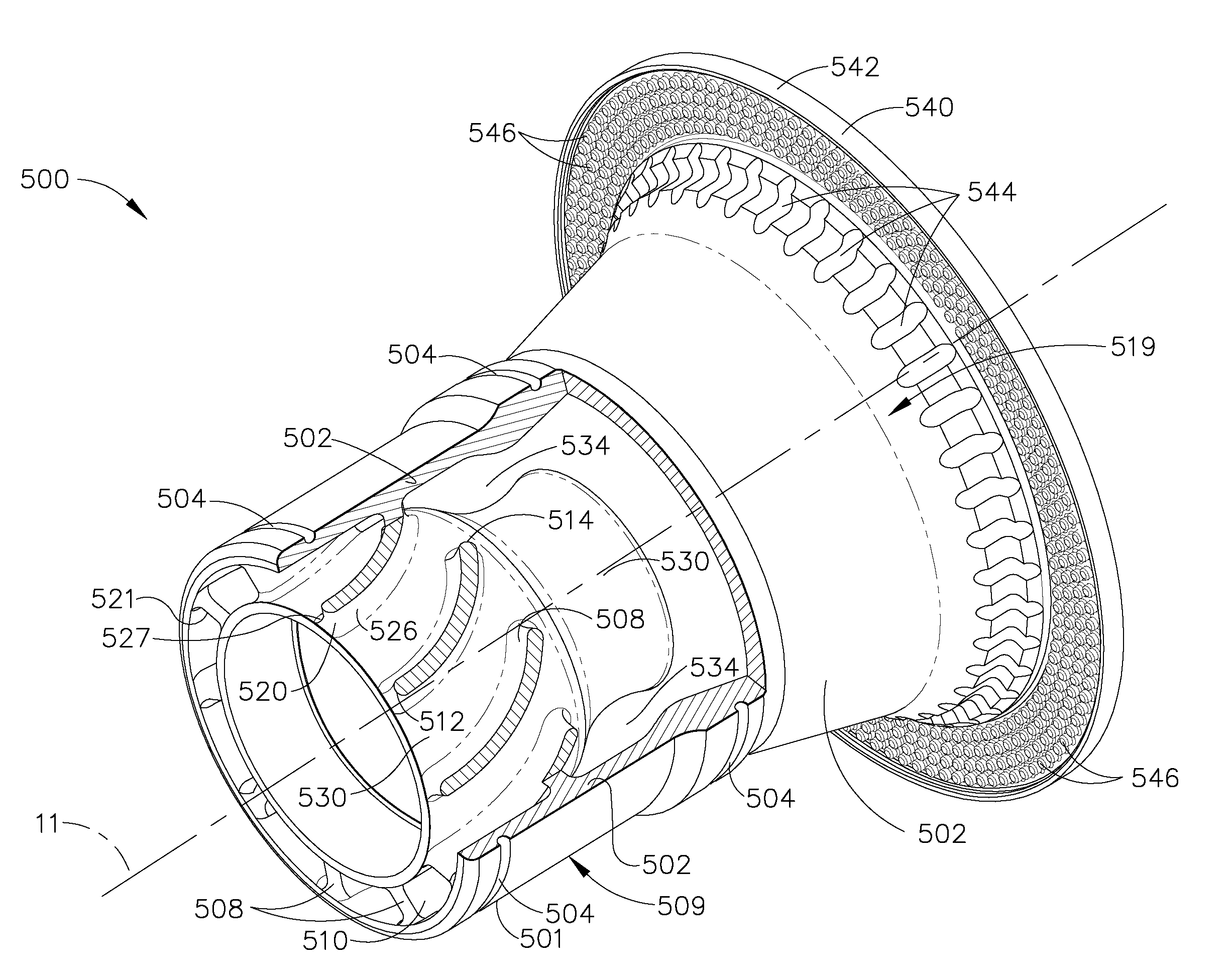
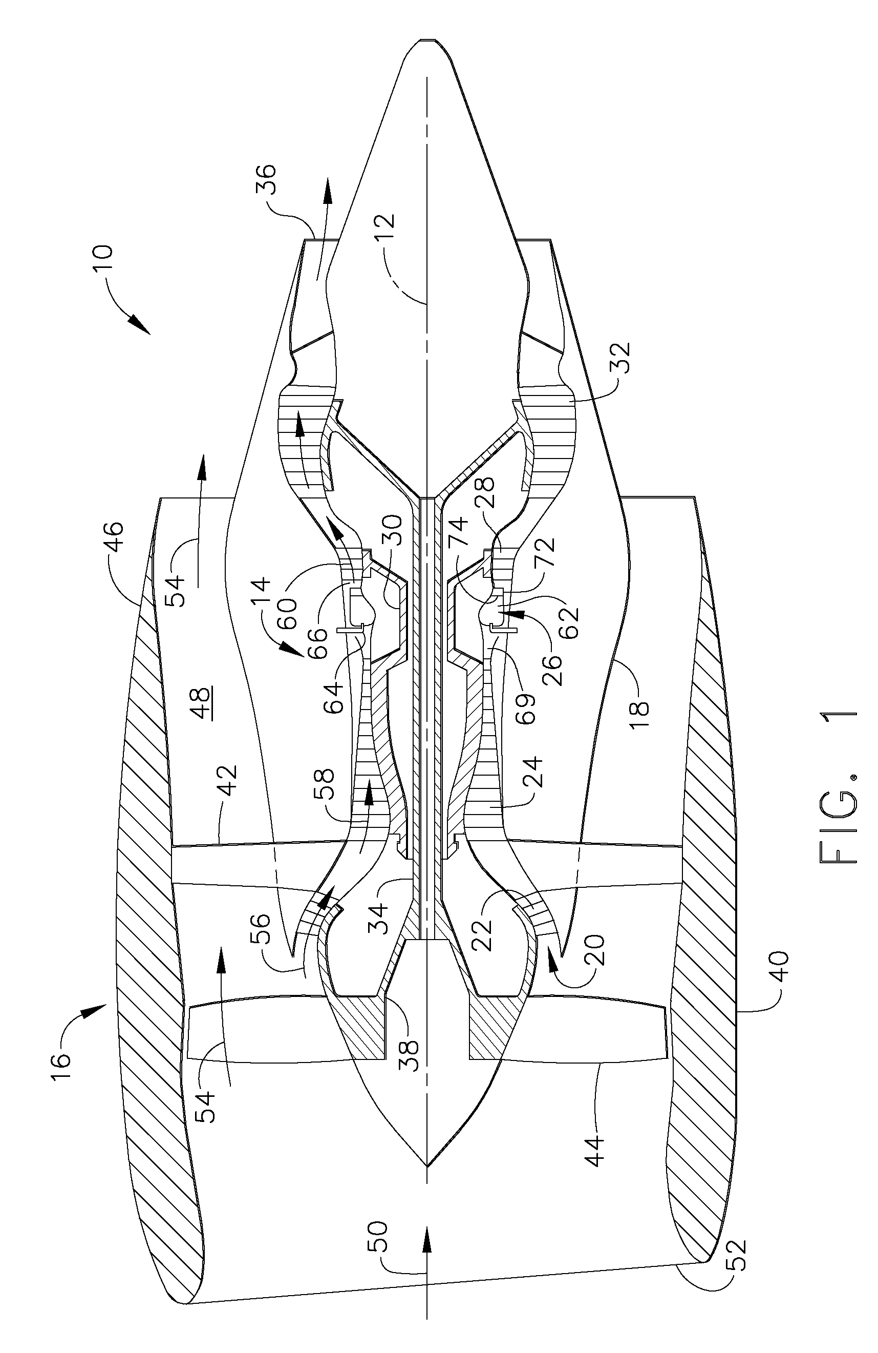
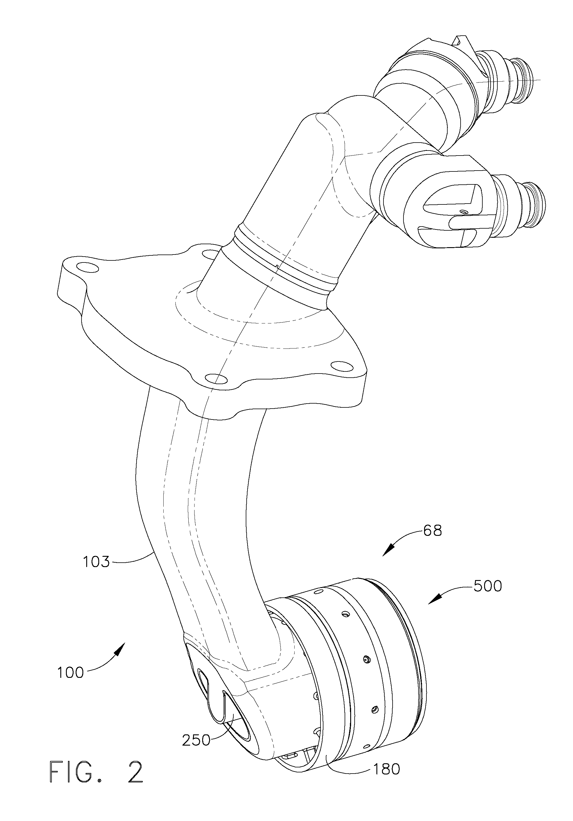
[0022]Referring now to the drawings in detail, wherein identical numerals indicate the same elements throughout the figures, FIG. 1 shows in diagrammatic form an exemplary gas turbine engine 10 (high bypass type) incorporating an exemplary fuel nozzle 100 having an exemplary embodiment of a venturi (such as items 500, shown in the figures and described herein) used for promoting mixing of air with the fuel in the fuel nozzle 100. The exemplary gas turbine engine 10 has an axial centerline axis 12 therethrough for reference purposes. Engine 10 preferably includes a core gas turbine engine generally identified by numeral 14 and a fan section 16 positioned upstream thereof. Core engine 14 typically includes a generally tubular outer casing 18 that defines an annular inlet 20. Outer casing 18 further encloses and supports a booster 22 for raising the pressure of the air that enters core engine 14 to a first pressure level. A high pressure, multi-stage, axial-flow compressor 24 receives ...


PUM

PropertyMeasurementUnit
Particle sizeaaaaaaaaaa

Abstract

A method for fabricating a unitary venturi is disclosed, the method comprising the steps of determining three-dimensional information of the unitary venturi having an annular venturi wall and a swirler having a plurality of vanes arranged circumferentially around a swirler axis, converting the three-dimensional information into a plurality of slices that each define a cross-sectional layer of the unitary venturi, and successively forming each layer of the unitary venturi by fusing a metallic powder using laser energy. Exemplary embodiments are disclosed, showing a unitary venturi comprising an annular venturi wall having a swirler axis and a heat shield located at an end wherein unitary venturi is made by using a rapid manufacturing process. In one aspect of the invention, the rapid manufacturing process is a laser sintering process.

Description

CROSS-REFERENCE TO RELATED APPLICATIONS[0001]This Application claims priority to U.S. Provisional Application Ser. No. 61 / 044,116, filed Apr. 11, 2008, which is herein incorporated by reference in its entirety.BACKGROUND OF THE INVENTION[0002]This invention relates generally to venturis, and more specifically to unitary venturis having swirlers for promoting mixing of fuel and air and a heat shield for protection from combustion heat in fuel nozzles used in gas turbine engines.[0003]Turbine engines typically include a plurality of fuel nozzles for supplying fuel to the combustor in the engine. The fuel is introduced at the front end of a burner in a highly atomized spray from a fuel nozzle. Compressed air flows around the fuel nozzle and mixes with the fuel to form a fuel-air mixture, which is ignited by the burner. Because of limited fuel pressure availability and a wide range of required fuel flow, many fuel injectors include pilot and main nozzles, with only the pilot nozzles bei...

Claims


Application Information

Patent Timeline
IPC IPC(8): F02C7/22B22F7/00B22F5/00B22F3/105B23K26/34
CPCB23P6/007Y10T29/49318F23D2900/00018F23D2900/14701F23R3/14F23R3/283F23R3/286F23R3/343F23R2900/00018Y02T50/675B22F2007/068B23P6/005Y10T29/49746Y10T29/4932B23P2700/13F23D2213/00F23R3/28Y10T137/265B33Y80/00Y02P10/25Y02E30/30F23C7/004F02C7/222B23P6/00F23D11/38Y02T50/60
Inventor MCMASTERS, MARIE ANNBENJAMIN, MICHAEL A.MANCINI, ALFRED
Owner GENERAL ELECTRIC CO
Learn More