Quarter wave stub surge suppressor with coupled pins

a quarter wave stub and surge suppressor technology, applied in waveguide devices, emergency protective arrangements for limiting excess voltage/current, circuit-breaking switches, etc., can solve problems such as increased installation errors, unsatisfactory effects, and dangerous energy levels of qws surge suppressors connected to transmission lines

Inactive Publication Date: 2009-10-08
JOHN MEZZALINGUA ASSOC INC
View PDF47 Cites 7 Cited by
  • Summary
  • Abstract
  • Description
  • Claims
  • Application Information

AI Technical Summary

Benefits of technology

[0006]It is a primary object of the present invention to provide a device for suppressing surges of low frequency electromagnetic signals in an RF transmission line, while allowing the desired RF signals to pass through.
[0007]It is a further object of the present invention to provide a device for suppressing surges of low frequency signals in an RF transmission line with a pass through signal bandwidth exceeding the bandwidth of the devices employing the conventional QWS design.
[0008]It is a further object of the present invention to provide a device for suppressing surges of low frequency signals in an RF transmission line with a high passband return loss and a high surge attenuation level.
[0009]It is a further object of the present invention to provide a symmetrical device for suppressing surges of low frequency signals in an RF transmission line, which is bi-directionally insertable into the transmission line which can be provided by a coaxial cable.

Problems solved by technology

In radio frequency (RF) signal transmission lines, typically transmitting electromagnetic signals with the frequencies over 1 MHz, undesirable effects can occur if a strong surge (e.g., caused by lightning) is transmitted to sensitive electronic devices coupled to the transmission line.
Besides, the surge signals that can be allowed to pass by the traditional QWS surge suppressors can have energy levels which are dangerous for sensitive electronic equipment connected to the transmission line.
The asymmetrical insertion requirement can significantly increase the rate of installation errors.

Method used


Image

  • Quarter wave stub surge suppressor with coupled pins
  • Quarter wave stub surge suppressor with coupled pins
  • Quarter wave stub surge suppressor with coupled pins

Examples


Embodiment Construction

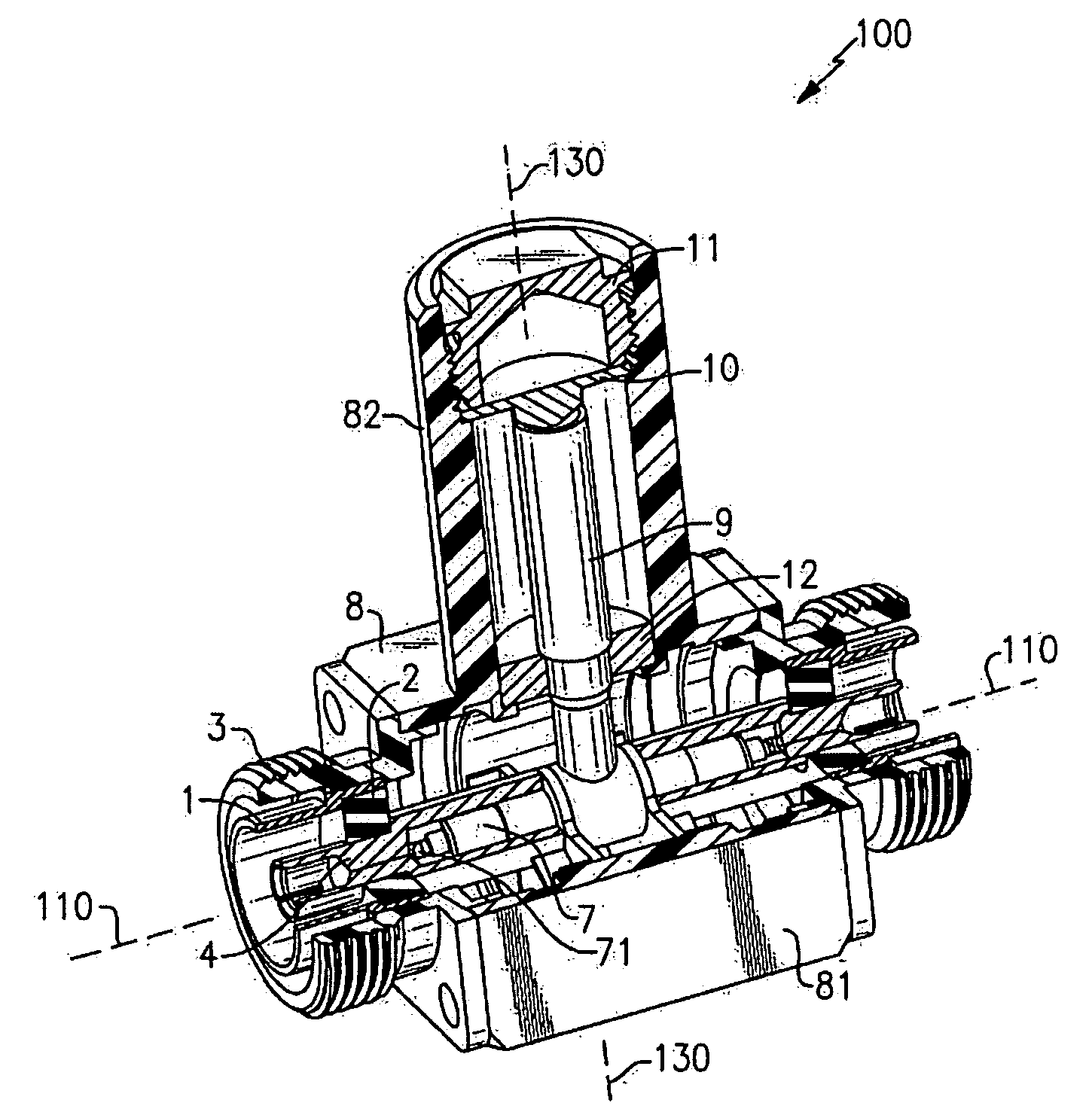
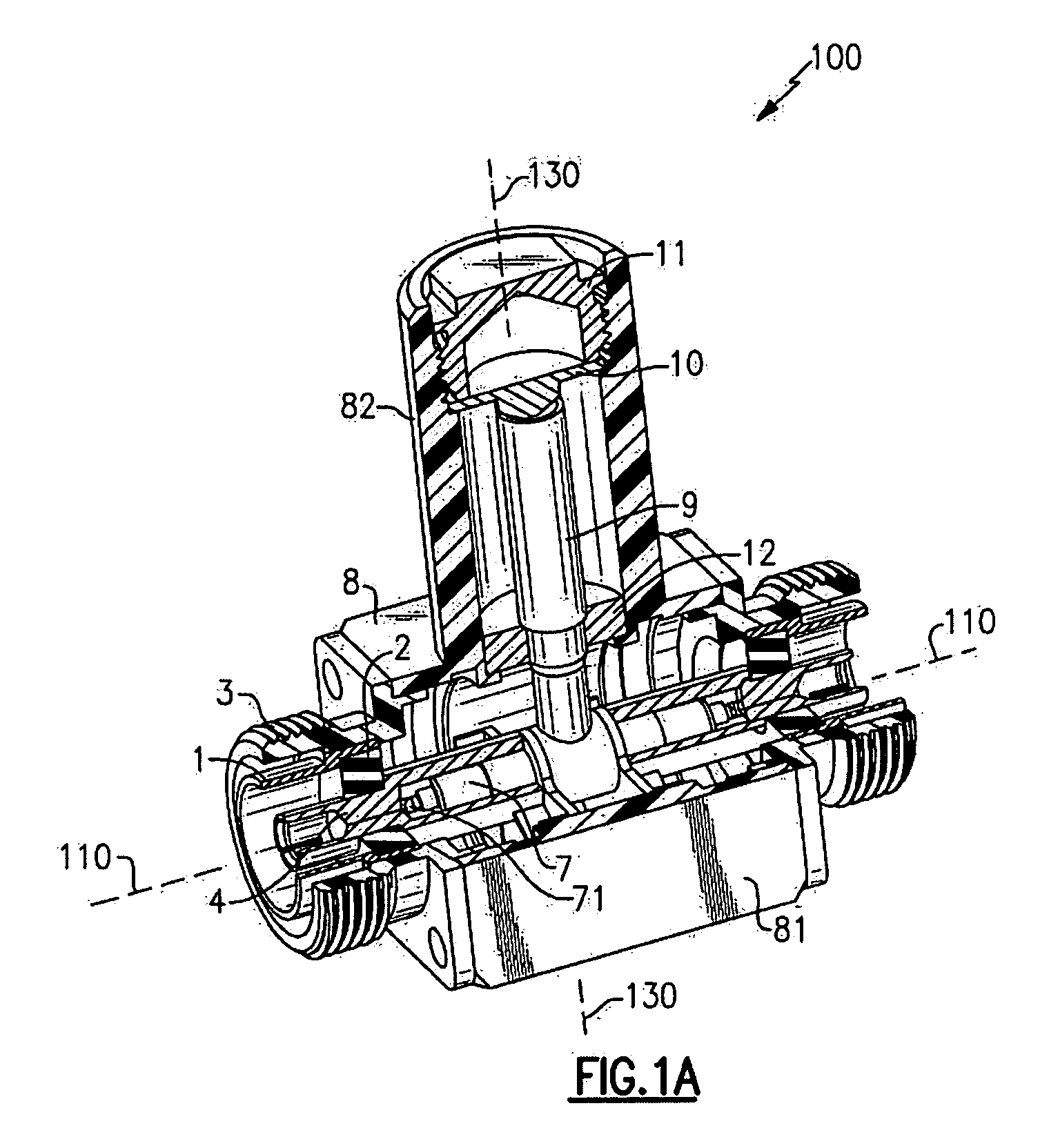
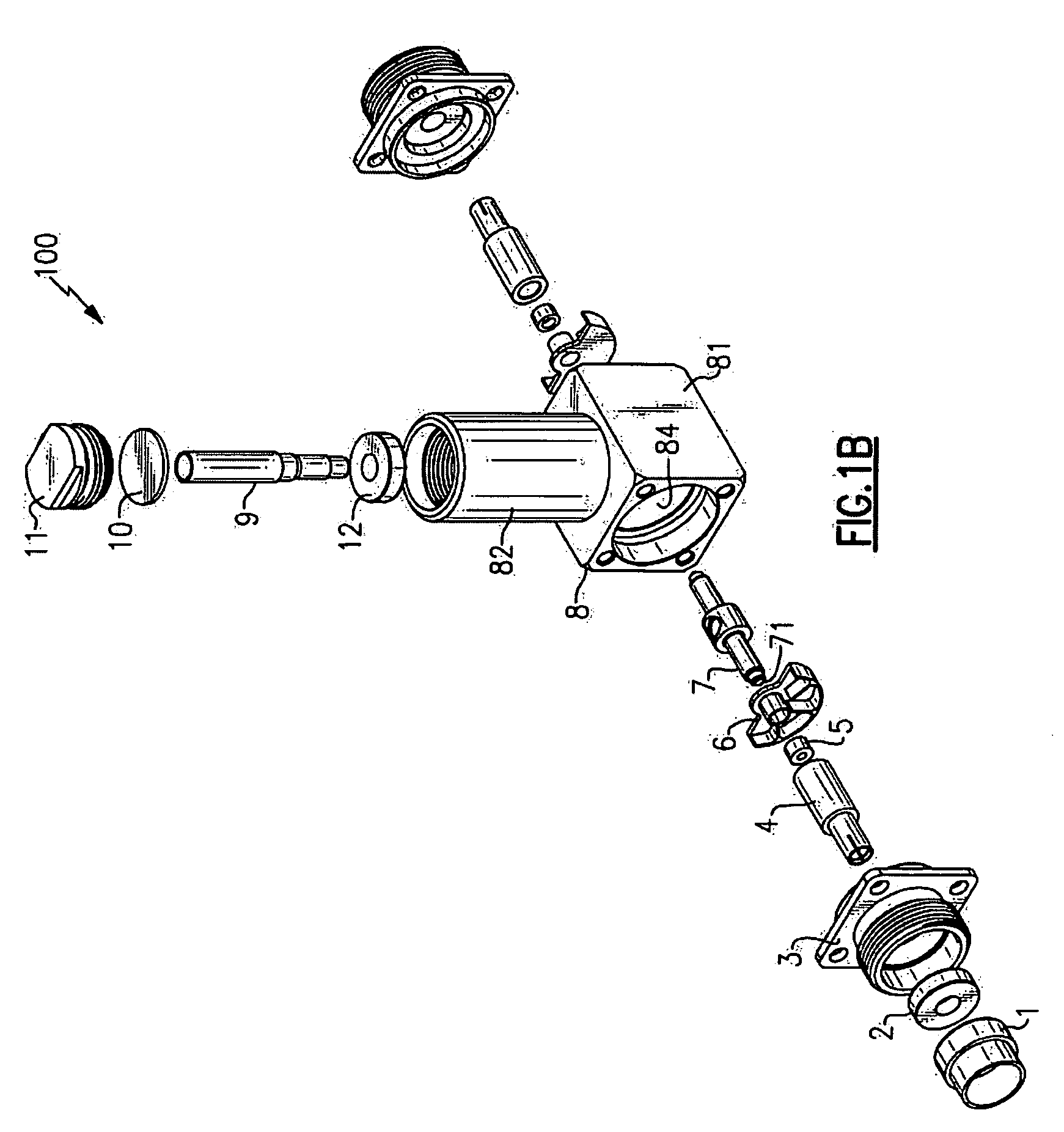
[0021]One embodiment of a surge suppressor in accordance with the present invention is described referencing FIGS. 1a and 1b which illustrate cutaway and exploded views of a symmetrical single-stub surge suppressor, and FIG. 1c which illustrates a cutaway view of the surge suppressor with the housing being removed. A skilled artisan would appreciate the fact that the scope and spirit of the present invention include multi-stub designs of the surge suppressor.

[0022]In the embodiment shown in FIGS. 1a-1c, the surge suppressor 100 extending along a longitudinal axis 110, is generally symmetrical relatively to the vertical axis 130, the latter being the axis of symmetry of the stub 9. The symmetrical design feature allows symmetrical bi-directional insertion of the surge suppressor 100 into a cable that provides the RF signal transmission. The symmetrical design feature further allows showing in the exploded view and describing only one component of each pair of the symmetrical componen...


PUM


Abstract

A surge suppressor for protecting electronic equipment by suppressing damaging surges of low frequency signals in a radio frequency (RF) transmission line, while allowing RF signals of a desired frequency range to pass through the transmission line. The surge suppressor can comprise a housing, a center pin connected to a stub, and at least one interface pin conductively coupled to the cable and capacitively coupled to the center pin. The surge suppressor can have a signal pass through bandwidth approximately 10 times exceeding the bandwidth of traditional quarter wavelength stub (QWS) devices, a higher return loss, and higher surge attenuation level. The surge suppressor can be symmetrically insertable into a cable providing an RF communication line.

Description

FIELD OF THE INVENTION[0001]This invention relates generally to surge protectors, and more particularly to quarter wave stub (QWS) surge protectors employed in high-frequency signal transmission lines.BACKGROUND OF THE INVENTION[0002]In radio frequency (RF) signal transmission lines, typically transmitting electromagnetic signals with the frequencies over 1 MHz, undesirable effects can occur if a strong surge (e.g., caused by lightning) is transmitted to sensitive electronic devices coupled to the transmission line. Lightning can produce strong surge signals ranging in frequency from 0 (direct current) to 1 MHz. Therefore, a surge suppressor should prevent surges of low frequency signals from passing through the transmission line, while allowing the desired RF signals to pass freely.[0003]Surge suppressors insertable into a transmission line in series with the equipment being protected can employ quarter wave stubs (QWS) which are seen as a short circuit to the ground by low frequen...

Claims


Application Information

Patent Timeline
Patent Type & Authority Applications(United States)
IPC IPC(8): H02H3/22
CPCH01P1/202
Inventor ALKAN, ERDOGANOLCEN, AHMET BURAK
Owner JOHN MEZZALINGUA ASSOC INC
Why Eureka
Try Eureka