Transformer inrush current suppression method, device and equipment

A technology for inrush current suppression and transformers, applied in the field of transformers, can solve problems such as inability to effectively suppress excitation inrush currents of each phase

Active Publication Date: 2020-01-07
GUANGDONG POWER GRID CO LTD +1
View PDF5 Cites 5 Cited by
  • Summary
  • Abstract
  • Description
  • Claims
  • Application Information

AI Technical Summary

Problems solved by technology

[0004] This application provides a transformer inrush suppression method, device and equipment, which are used to solve the problem that the existing transformer inrush suppression method needs to rely on known transformer remanence, and cannot effectively suppress the excitation inrush current of each phase under the condition of unknown transformer remanence question

Method used


Image

  • Transformer inrush current suppression method, device and equipment
  • Transformer inrush current suppression method, device and equipment
  • Transformer inrush current suppression method, device and equipment

Examples


Embodiment Construction

[0046] In order to enable those skilled in the art to better understand the solutions of the application, the technical solutions in the embodiments of the application will be clearly and completely described below in conjunction with the drawings in the embodiments of the application. Obviously, the described embodiments are only It is a part of the embodiments of this application, but not all the embodiments. Based on the embodiments in this application, all other embodiments obtained by those of ordinary skill in the art without creative work fall within the protection scope of this application.

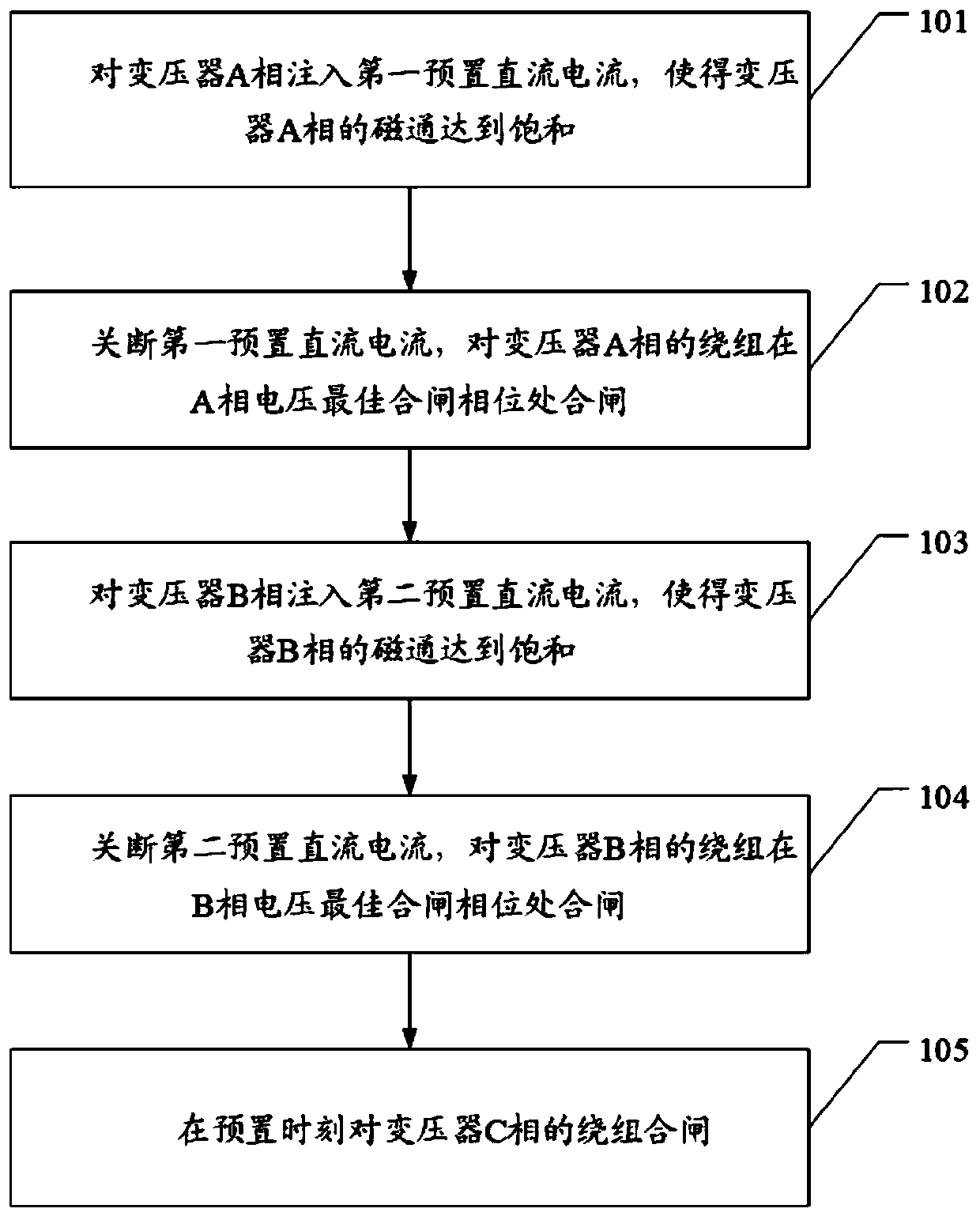
[0047] For ease of understanding, please refer to figure 1 , An embodiment of a transformer inrush current suppression method provided in this application includes:

[0048] Step 101: Inject a first preset DC current into the transformer A phase, so that the magnetic flux of the transformer A phase reaches saturation.

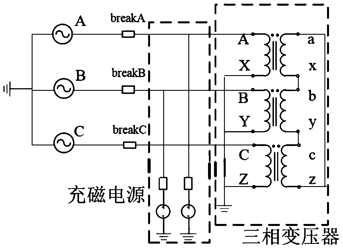
[0049] It should be noted that please refer to figure 2 , figure...


PUM


Abstract

The invention discloses a transformer inrush current suppression method, device and equipment. Based on the three-phase split-phase premagnetization and split-phase phase-controlled closing of a transformer, the winding flux of each phase is charged to the saturation flux one by one, and then, closing is carried out one by one, so that the inrush flow of each phase is effectively suppressed, and excitation inrush current is hardly generated in the whole process; and the residual magnetism of an iron core does not need to be known, and thus the technical problems that the existing transformer inrush current suppression method needs to depend on the known residual magnetism of the transformer, and the excitation inrush current of each phase cannot be effectively suppressed under the condition that the residual magnetism of the transformer is unknown are solved.

Description

Technical field [0001] This application relates to the technical field of transformers, and in particular to a method, device and equipment for suppressing inrush current of a transformer. Background technique [0002] Transformers often generate magnetizing inrush current during the closing process. The inrush current may be as high as 10 times the rated current. These large currents will significantly heat the windings and cause insulation degradation. The mechanical force of the magnetizing inrush current is at the same level as the rated breaking force. , A large inrush current is likely to cause mechanical damage to the transformer. [0003] Because of its excellent short-circuit current limiting capability, high-impedance transformers are more and more widely used in power grids. However, in field applications, there have also been multiple inrush currents generated by high-impedance transformers during the closing process, leading to higher-level lines The misoperation of t...

Claims


Application Information

Patent Timeline
Patent Type & Authority Applications(China)
IPC IPC(8): H02H9/00H01F27/42
CPCH02H9/002H01F27/42H02H7/04
Inventor 王育学黄明辉李一泉刘玮邓旭阳陈桥平刘世丹刘琨王增超朱晓华
Owner GUANGDONG POWER GRID CO LTD
Why Eureka
Try Eureka