Blowing and discharging fan

A technology for supplying and exhausting air and motors, which is applied to mechanical equipment, machines/engines, liquid fuel engines, etc., and can solve problems such as noise, pressure fluctuations, and reduced air supply capacity

Active Publication Date: 2009-03-11
株式会社瑞典
View PDF3 Cites 6 Cited by
  • Summary
  • Abstract
  • Description
  • Claims
  • Application Information

AI Technical Summary

Problems solved by technology

[0007] If such a surge occurs, pressure fluctuations and vibrations will occur, and the sound resonating with the fan sound of the blade 3b will cause noise (sound pressure level) and a decrease in air blowing capacity.

Method used


Image

  • Blowing and discharging fan
  • Blowing and discharging fan
  • Blowing and discharging fan

Examples


Embodiment Construction

[0027] A preferred embodiment of the present invention will be described below with reference to the accompanying drawings.

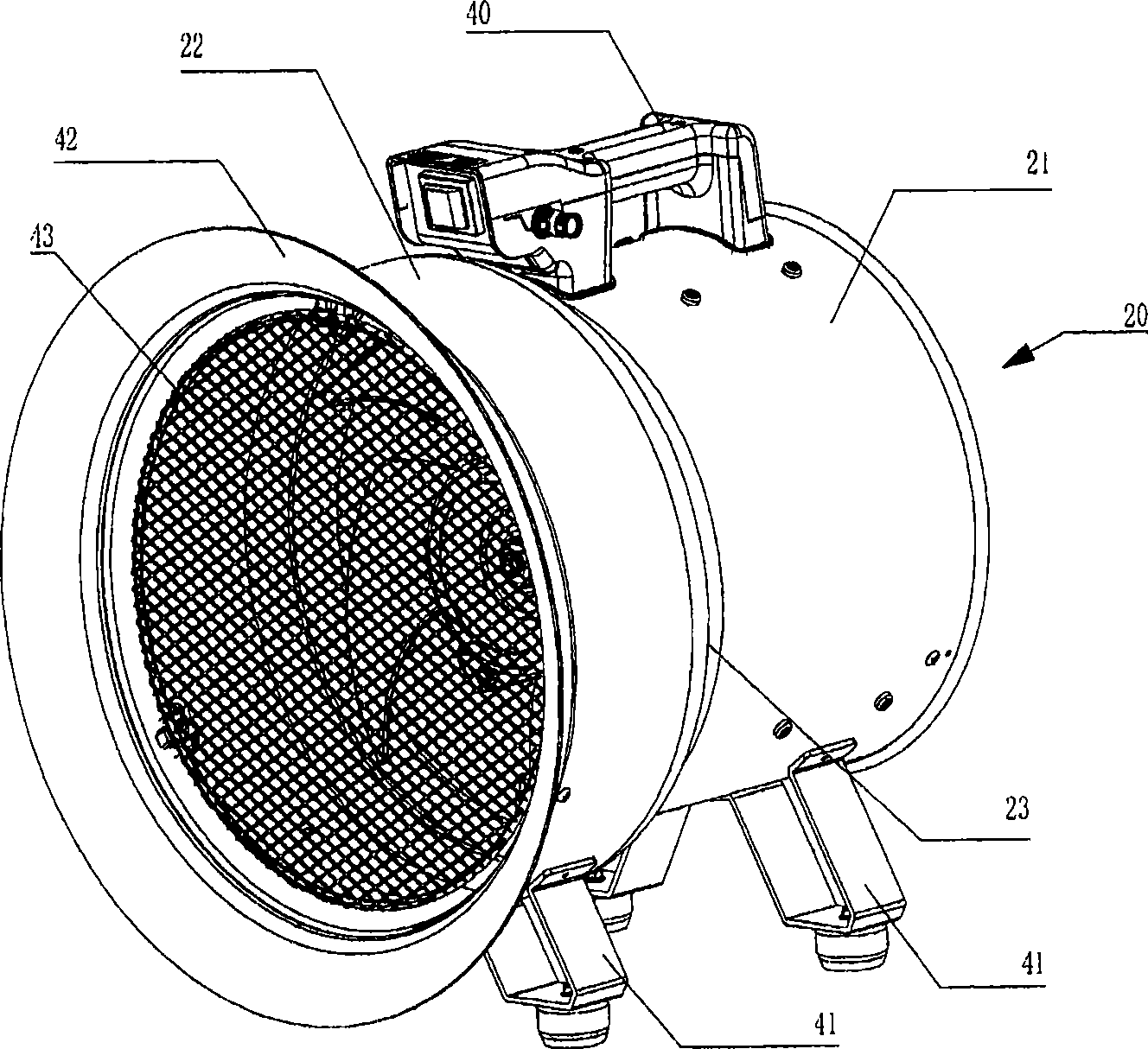
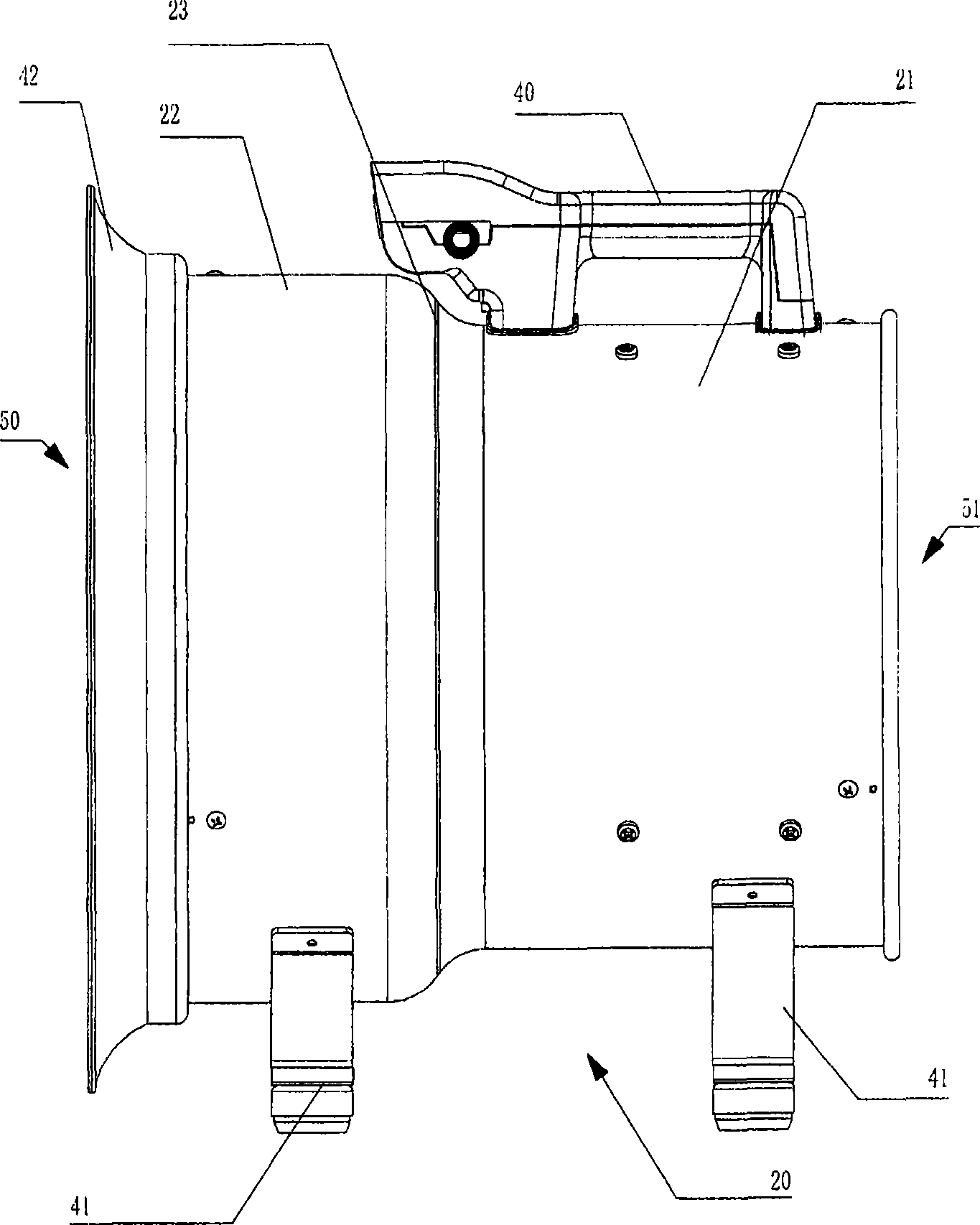
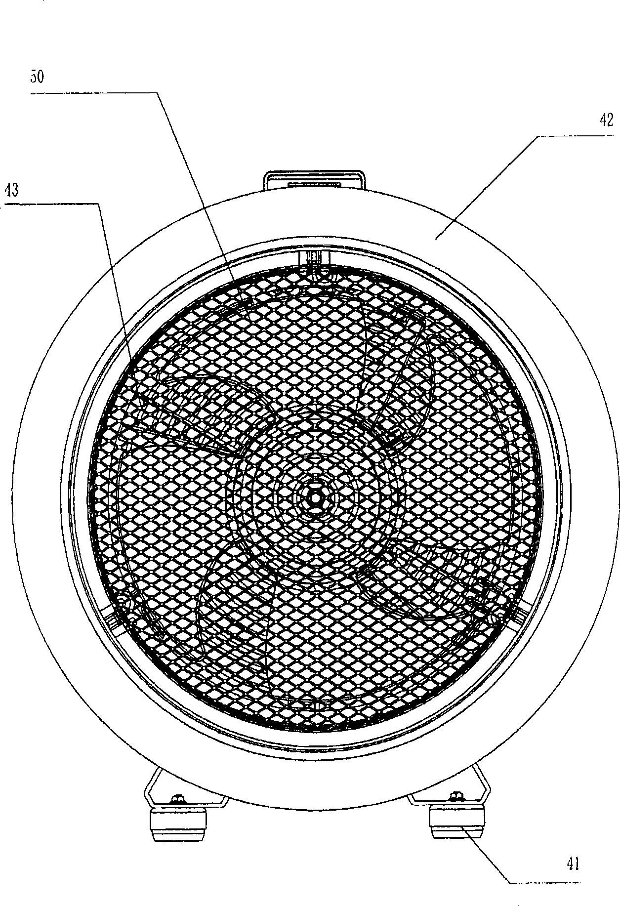
[0028] figure 1 is a perspective view of the present invention, figure 2 is the main view, image 3 is the left view, Figure 4 is the right side view, Figure 5 It is a front view in which the casing 20 is cut away so that the internal structure can be observed.

[0029] Such as figure 1 , figure 2 As shown, the casing 20 of the air blower of the present invention is composed of a large-diameter expanded tube part 22, a diameter-reduced reduced-diameter tube part 23, and a small-diameter main tube part from the suction port 50 side toward the discharge port 51 side. 21 is continuously formed into a substantially cylindrical shape. Such as image 3 As shown in FIG. 22 , the bell mouth 2 is provided on the expanded tube portion 22 , and a mesh safety cover 43 capable of ventilation is provided on the suction port 50 . Additionally, if Figu...


PUM


Abstract

In an exhaust blowing fan, if surging occurs, the changing and vibration of the pressure generate, and the changing and the vibration as well as sound syntonizing with the sound of blades together generate noise (sound pressure level) and lead blow-in capability to decline. Therefore, the invention aims to provide an exhaust blowing fan which inhibits the cause of surging as possible namely generation of swirling flow. The exhaust blowing fan comprises an impeller consisting of a shaft hub and a plurality of blades arranged around the shaft hub, a motor used to rotate the impeller rotate, and a motor shell which receives the impeller and the motor and is approximately of a cylindrical shape, wherein the shell is formed by connecting a tube expanding cylinder part with large diameter and a main tube cylinder part with small diameter through a reducing tube cylinder part with gradually-reducing diameter. In addition, The middle position of the axial height of the blades is set at a place where the dividing line of the reducing tube cylinder part and the main tube cylinder part is at distance which is less than 20 percent of the height of the axis of the blades from the axis of the blades forward and backward respectively.

Description

technical field [0001] The present invention relates to a supply and exhaust fan used for local ventilation or drying of flowers, dispelling heat, air circulation and the like. Background technique [0002] As an exhaust fan for local ventilation or flower drying, heat removal, air circulation, etc., in the past, it was generally as follows Figure 10 the shape shown. That is, the bell mouth 2 is provided on the suction side of the cylindrical casing 1, and the impeller 3 composed of the hub 3a and the plurality of blades 3b arranged around the hub 3a is arranged in the casing 1, and the same configuration is used in the casing. A motor (not shown) inside 1 rotates the impeller 3 to discharge air from the opposite side of the suction port. [0003] In addition, there is a blower that achieves reduction in power consumption and improvement in air blowing function, and there are JP-A-2003-13892 and JP-A-2007-92671 as patent documents describing such an air blower. [0004] [...

Claims


Application Information

Patent Timeline
Patent Type & Authority Applications(China)
IPC IPC(8): F04D25/08F04D29/66F04D29/52F04D29/38
Inventor 片田耕三松本纯也堤盛葵中谷文昭
Owner 株式会社瑞典
Why Eureka
Try Eureka