
Electrolytic Capacitor Assembly Containing a Resettable Fuse

a technology of electrolytic capacitors and fuse capacitors, which is applied in the direction of fixed capacitors, positive temperature coefficient thermistors, fixed capacitor details, etc., can solve the problems of resettable fuse capacitors, failure to and failure to fully meet the requirements of many commercial applications

Inactive Publication Date: 2009-10-01
KYOCERA AVX COMPONENTS CORP
View PDF57 Cites 13 Cited by
  • Summary
  • Abstract
  • Description
  • Claims
  • Application Information

AI Technical Summary

Benefits of technology

The present invention is about a fused electrolytic capacitor assembly and a method of making it. The assembly includes an electrolytic capacitor element with a resettable fuse containing a positive temperature coefficient material. The fuse is covered with a stress absorbing material and the assembly is encapsulated. The technical effect of this invention is that it provides a reliable and flexible way to protect the fuse and ensure proper functionality of the electrolytic capacitor assembly.

Problems solved by technology

The fuse disintegrates in response to the excessive current resulting from this discharge, which breaks the electrical connection between the failed element and the collector bus.
One problem with such conventional fused capacitors, however, is that they can no longer function in the desired manner.
Upon cooling, the fuse may contract to close the circuit, thereby rendering the fuse at least partially “resettable.” Unfortunately, resettable fuse capacitors, such as described in Kamigawa, et al., are still not completely satisfactory for use in many commercial applications.
Without intending to be limited by theory, the present inventors believe that one of the problems with such capacitors is that the resin used to encapsulate the electrolytic capacitor limits the expansion of the resettable fuse to such an extent that it does not function to its full capacity.
Further, the thermal stresses induced by expansion of the fuse may also lead to the formation of defects in the encapsulation resin.

Method used


Image

  • Electrolytic Capacitor Assembly Containing a Resettable Fuse
  • Electrolytic Capacitor Assembly Containing a Resettable Fuse
  • Electrolytic Capacitor Assembly Containing a Resettable Fuse

Examples


example

[0057]70,000 μFV / g tantalum powder (HC Starck) was pressed into pellets and sintered to form a porous electrode body of size 5.4×3.75×1.25 mm. Anodic oxidation was then carried out in an aqueous solution containing phosphoric acid. The voltage was chosen to obtain a targeted capacitance of 330 μF at a rated voltage of 6.3V. After anodic oxidation, the pellets were coated with a manganese dioxide layer, a graphite coating and a silver coating by conventional technology known to the skilled in art.

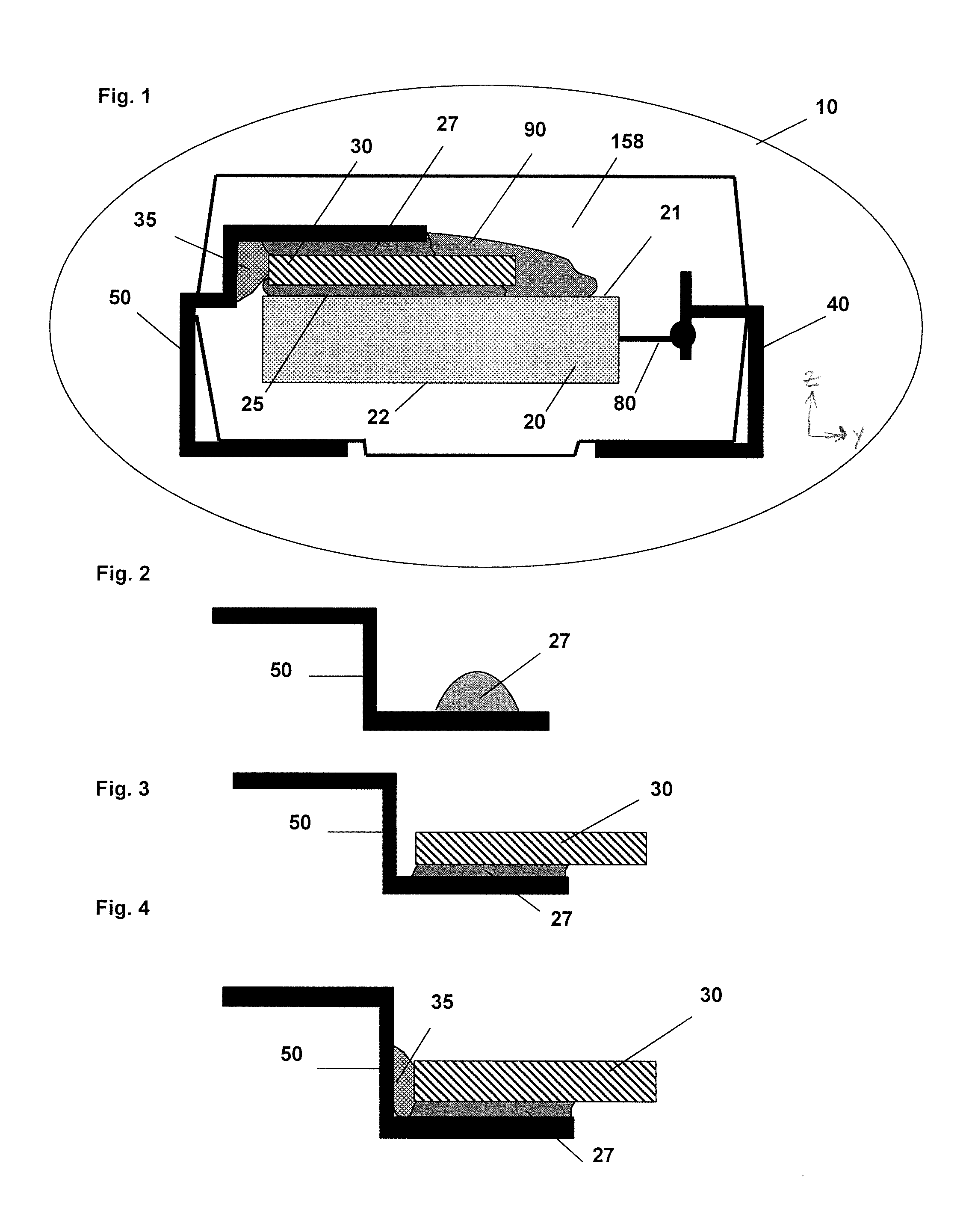
[0058]PPTC fuses were obtained from Tyco Raychem under the designation “Fluo-2”, which had a size of 3.6×3.6×0.5 mm. The fuses were based on a fluoroelestomer polymer filled with nickel conductive particles and contained gold-plated nickel contact layers on the large areas. The pellets were assembled with the PPTC fuses to the D case (EIA 7348) as shown in FIGS. 2-7. More specifically, a flexible silver loaded epoxy adhesive 27 (XCE80239 Emerson & Cuming) was dispensed into the pocket of a l...


PUM

PropertyMeasurementUnit
densityaaaaaaaaaa
densityaaaaaaaaaa
densityaaaaaaaaaa

Abstract

A fused electrolytic capacitor assembly that offers improved performance characteristics in a convenient and space-saving package is provided. More specifically, the fused electrolytic capacitor assembly contains an electrolytic capacitor element and a resettable fuse contained within a case. The capacitor assembly also contains a stress absorbing material that is positioned adjacent to and in contact with the resettable fuse. By selecting a stress absorbing material having a certain modulus and a certain degree of inherent flexibility, the present inventors believe the resettable fuse is better able to expand to its full capacity upon exposure to an excessive current. In this manner, the resettable fuse is able to better function during use.

Description

BACKGROUND OF THE INVENTION[0001]Solid electrolytic capacitors, such as tantalum capacitors, are traditionally known for their high capacitance value and compactness. Fuses are often employed in such capacitors to prevent burning upon exposure to overcurrent conditions. A typical fuse assembly employs a small conductive wire that disintegrates in response to excessive electrical current. Typically, one end of the fuse is soldered to a metal conducting foil edge of an electrolytic capacitor element and the other end of the fuse is soldered to a metal collector bus. When an electrolytic capacitor element fails, it creates a short circuit through which energy stored therein and in the circuit may discharge. The fuse disintegrates in response to the excessive current resulting from this discharge, which breaks the electrical connection between the failed element and the collector bus.[0002]One problem with such conventional fused capacitors, however, is that they can no longer function ...

Claims


Application Information

Patent Timeline
Patent Type & Authority Applications(United States)
IPC IPC(8): H01G9/022H01G9/15H01H85/06H01G9/042H01C7/02H01G9/004H01G9/028H01G9/12
CPCH01G2/16Y10T29/417H01G9/28H01G9/0003H02H9/026
Inventor PASCENKO, IVAN
Owner KYOCERA AVX COMPONENTS CORP
Learn More