
Modulated electromagnetic stirring of metals at advanced stage of solidification

Inactive Publication Date: 2009-10-01
ABB INC
View PDF15 Cites 15 Cited by
  • Summary
  • Abstract
  • Description
  • Claims
  • Application Information

AI Technical Summary

Benefits of technology

[0012]In accordance with another aspect of the present invention, there is provided a method of electromagnetic stirring a metallic melt. The method comprises: providing a first stirrer for generating a first rotating magnetic field that rotates about an axis extending through the melt, at an angular frequency of ω1; providing a second stirrer for generating a second rotating magnetic field that rotates at an a

Problems solved by technology

Rotational stirring of the melt within the mold produces turbulence and shear force at the solid-liquid interface.
Conventional rotational stirring, however, is not effective at an advanced stage of solidification of the melt, because any turbulence produced by rotational stirring is essentially limited to the solid-liquid interface.
The effectiveness of intermittent and alternating stirring, however, has proven to be limited since they do not produce significant turbulence in the melt beyond the solid-liquid interface.
In addition, the total stirring time available for stirring of continuously cast billets and blooms is limited by the 10 to 40 second period, depending on the cast product cross-section size and the related casting speed.
These modulation methods have proved to be effective at modulation periods of about 10 seconds, which also limits their usefulness in continuous casting of billets and blooms.

Method used


Image

  • Modulated electromagnetic stirring of metals at advanced stage of solidification
  • Modulated electromagnetic stirring of metals at advanced stage of solidification
  • Modulated electromagnetic stirring of metals at advanced stage of solidification

Examples


example ems

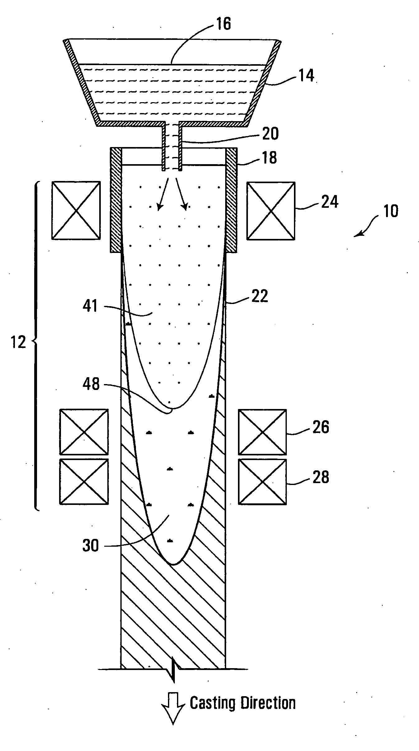
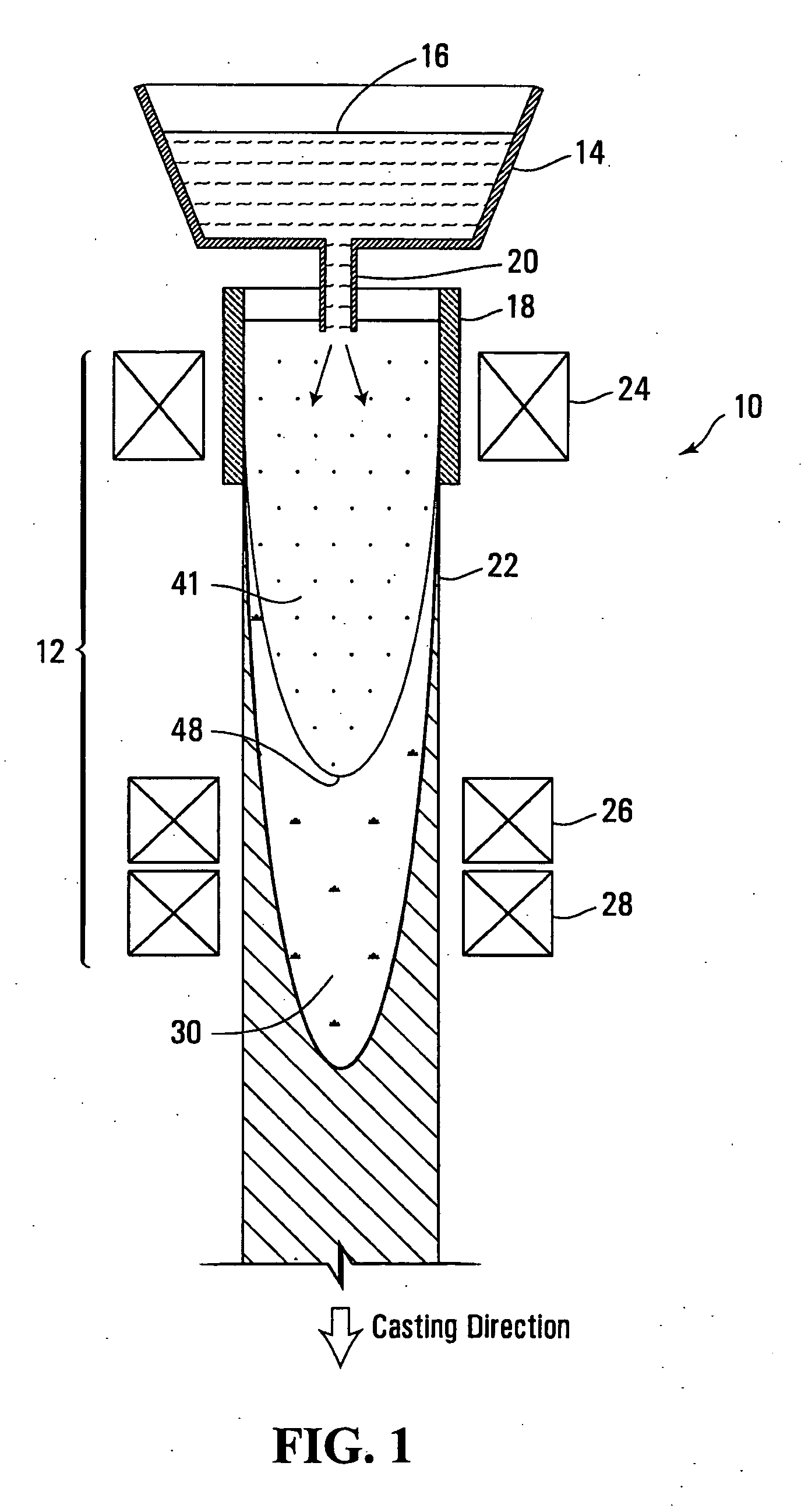
[0031 system 12, typically includes at least one electromagnetic stirrer 24 arranged about mold 18. Stirrer 24 could be arranged within the mold housing, or may be enclosed in a housing (not shown) surrounding the mold. As will become apparent, stirrer 24 is arranged to induce stirring motion within the melt inside mold 18 at an early stage of solidification. In the depicted embodiment only one stirrer 24 is arranged about mold 18 to induce rotational stirring of the melt in mold 18. Stirrer 24 could be replaced with a plurality (e.g. 2) of electromagnetic stirrers arranged about mold 18.

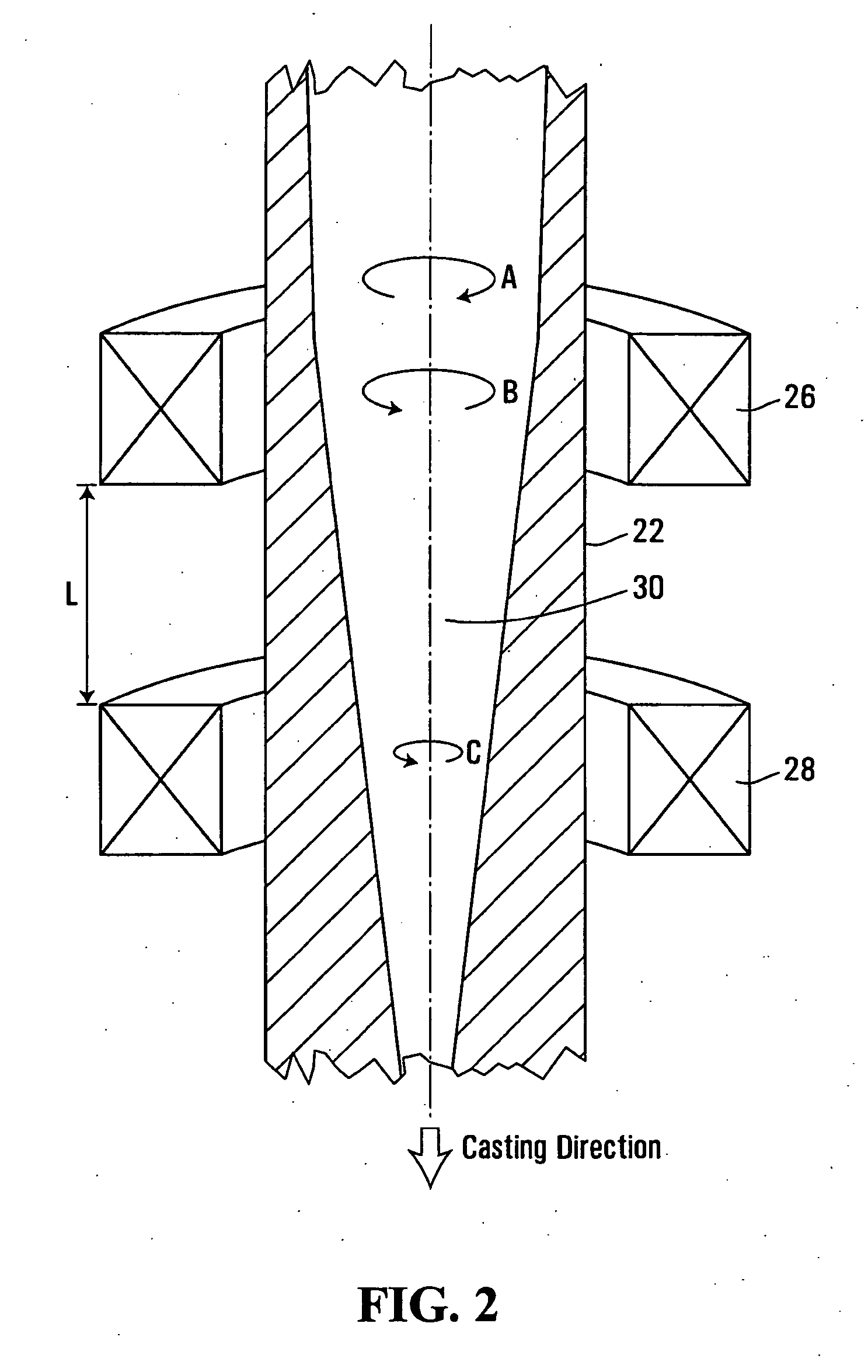
[0032]Additional at least two electromagnetic stirrers 26, 28 are positioned downstream of mold 18 about cast strand 22, at chosen positions detailed below. Again, stirrers 26, 28 are typically enclosed in a housing (not shown), and co-located in this housing.

[0033]At distances away from and downstream of mold 18, cast strand 22 progresses in its solidification, resulting in a shell of increasing th...


PUM

PropertyMeasurementUnit
Fractionaaaaaaaaaa
Frequencyaaaaaaaaaa
Temperatureaaaaaaaaaa

Abstract

A method and apparatus for electromagnetic stirring of molten metals at an advanced stage of solidification, as may be used in continuous casting of steel billets and blooms, are disclosed. At least first and second stirrers are provided for generating first and second rotating magnetic fields of a differing frequency about an axis of solidifying molten metal. The stirrers are arranged about the molten metal in sufficiently close proximity to each other so that their respective magnetic fields superpose to produce a modulated magnetic field. The magnetic fields of the respective stirrers may either have common or opposing rotational directions. The modulated stirring produced by the magnetic fields results in oscillating primary and secondary flows and hence turbulence within the melt bulk in the region wherein temperature of the melt on its central axis is below the liquidus level and at least 10% of substantially solidified material is formed. Turbulent flow created by this stirring method disrupts formation of crystalline structures in the melt bulk and mixes solute enriched melt of the central region with the bulk volume which subsequently results in improvements of the solidification structure and overall internal quality of the cast products.

Description

FIELD OF THE INVENTION[0001]The present invention relates to electromagnetic stirring and more particularly to electromagnetic stirring of liquid metals as they solidify. The invention may be used in continuous casting of steel, alloys, or other metallic melts, and in other solidification processes of these materials.BACKGROUND OF THE INVENTION[0002]Electromagnetic stirring (EMS) is commonly used in the production of continuously cast steel billets, blooms, and the like; the casting of different alloys; and other liquid metal casting and processing. Typically, A.C. electric current is applied to induction coils that surround the melt. The A.C. current excites a continuous rotating A.C. electromagnetic field that stirs a metal, such as in the production in continuous cast steel billets and blooms. For example, the A.C. field may stir the melt in the continuous casting mold, at an early stage of solidification.[0003]Rotational stirring of the melt within the mold produces turbulence a...

Claims


Application Information

Patent Timeline
IPC IPC(8): B22D27/02
CPCB01F13/0809B22D11/122B22D11/115B01F33/451
Inventor BEITELMAN, LEONID S.TALLBACK, GOTE R.LAVERS, J. DOUGLASCURRAN, CHRISTOPHER P.TALLBACK, ELS-MARIE
Owner ABB INC
Learn More