
Breathing assistance apparatus

a technology for osa and breathing assistance, which is applied in the field of breathing assistance equipment, can solve the problems of pressure sores, considerable discomfort for users, and osa sufferers usually experiencing daytime drowsiness and irritability, and achieves the effects of increasing treatment compliance, convenient use, and comfortable wear

Active Publication Date: 2009-10-01
FISHER & PAYKEL HEALTHCARE LTD
View PDF23 Cites 52 Cited by
  • Summary
  • Abstract
  • Description
  • Claims
  • Application Information

AI Technical Summary

Benefits of technology

[0017]It is an object of the present invention to attempt to provide a patient interface that goes some way to overcoming the abovementioned disadvantages in the prior art or which will at least provide the industry with a useful choice.

Problems solved by technology

Sufferers of OSA usually experience daytime drowsiness and irritability due to a lack of good continuous sleep.
Commonly, in prior mask configurations a good mask-to-face seal has been attained in many instances only with considerable discomfort for the user.
A common complaint of a user of CPAP therapy is pressure sores caused by the mask about the nose and face and in particular in the nasal bridge region of the user.
This problem is most crucial in those applications, especially medical applications, which require the user to wear such a mask continuously for hours or perhaps even days, hi such situations, the user will not tolerate the mask for long durations and optimum therapeutic or diagnostic objectives thus will not be achieved, or will be achieved with great difficulty and considerable user discomfort.
This headgear could be considered by many patients as cumbersome and uncomfortable.
Conventional nasal masks used for administrating CPAP treatment are also considered uncomfortable and cumbersome, and prior art nasal masks can be noisy due to air leaks.
These disadvantages in many cases are a formidable obstacle to patient acceptance of such treatment.
Therefore, a substantial number of patients either cannot tolerate treatment or choose to forego treatment.

Method used


Image

  • Breathing assistance apparatus
  • Breathing assistance apparatus
  • Breathing assistance apparatus

Examples


first embodiment

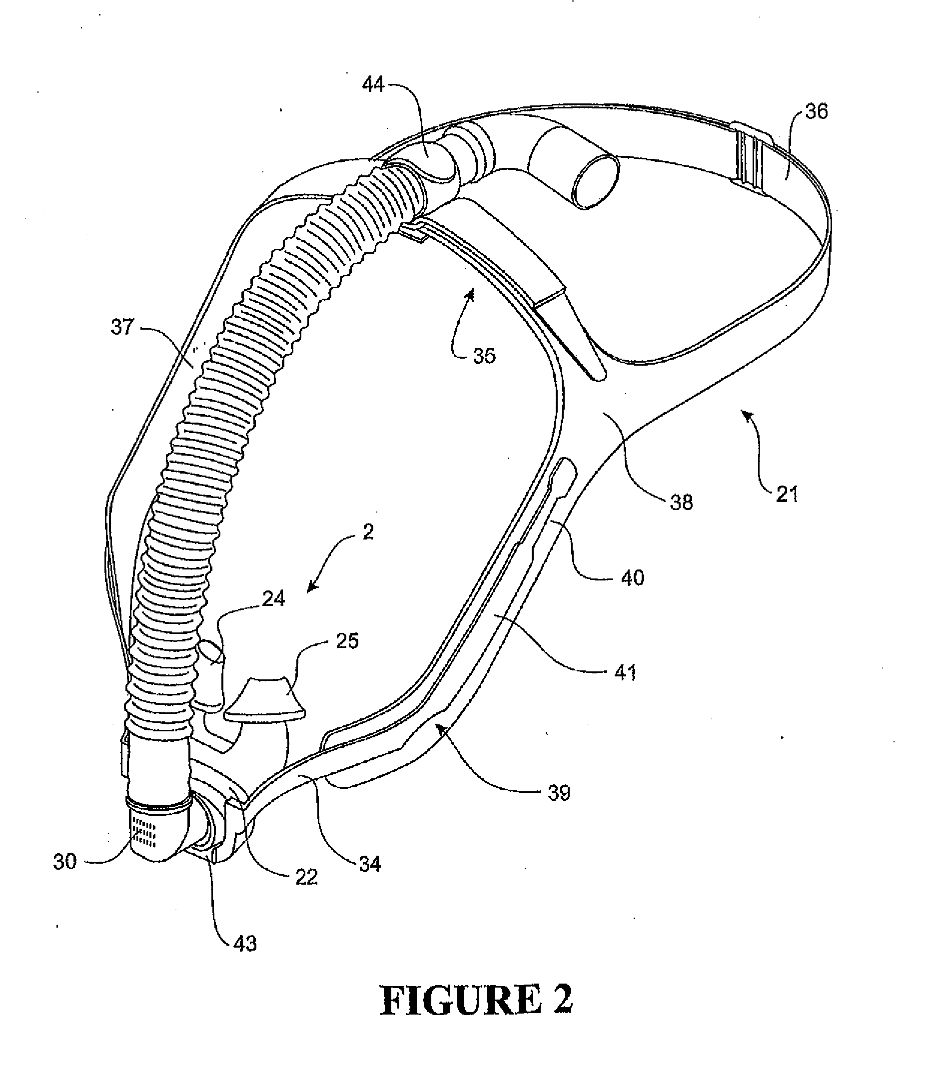
[0064]FIGS. 2 and 3 show a patient interface of the present invention. This patient interface is a nasal mask 2. The nasal mask 2 is comprised of a mask base 22 and body 23. The body 23 is substantially tubular with two nasal pillows 24, 25 extending from it. The nasal pillows 24, 25 are preferably frustoconical in shape and in use rest against a patient's nares, to substantially seal the patient's nares. The body 23 has an external lip 28 that frictionally fits in a channel in the mask base 22.

[0065]The body 23 and nasal pillows 24, 25 of the nasal mask of the present invention are shown in further detail in FIGS. 6 and 7. The body and pillows are preferably integrally moulded in a substantially flexible plastics material. In the preferred form this material is silicone, but other appropriate materials, such as, rubber, thermoset elastomer or thermoplastic elastomer, such as Kraton™ may be used.

[0066]The nasal pillows 24, 25 are preferably an elliptical cone and as such are tubular...

eighth embodiment

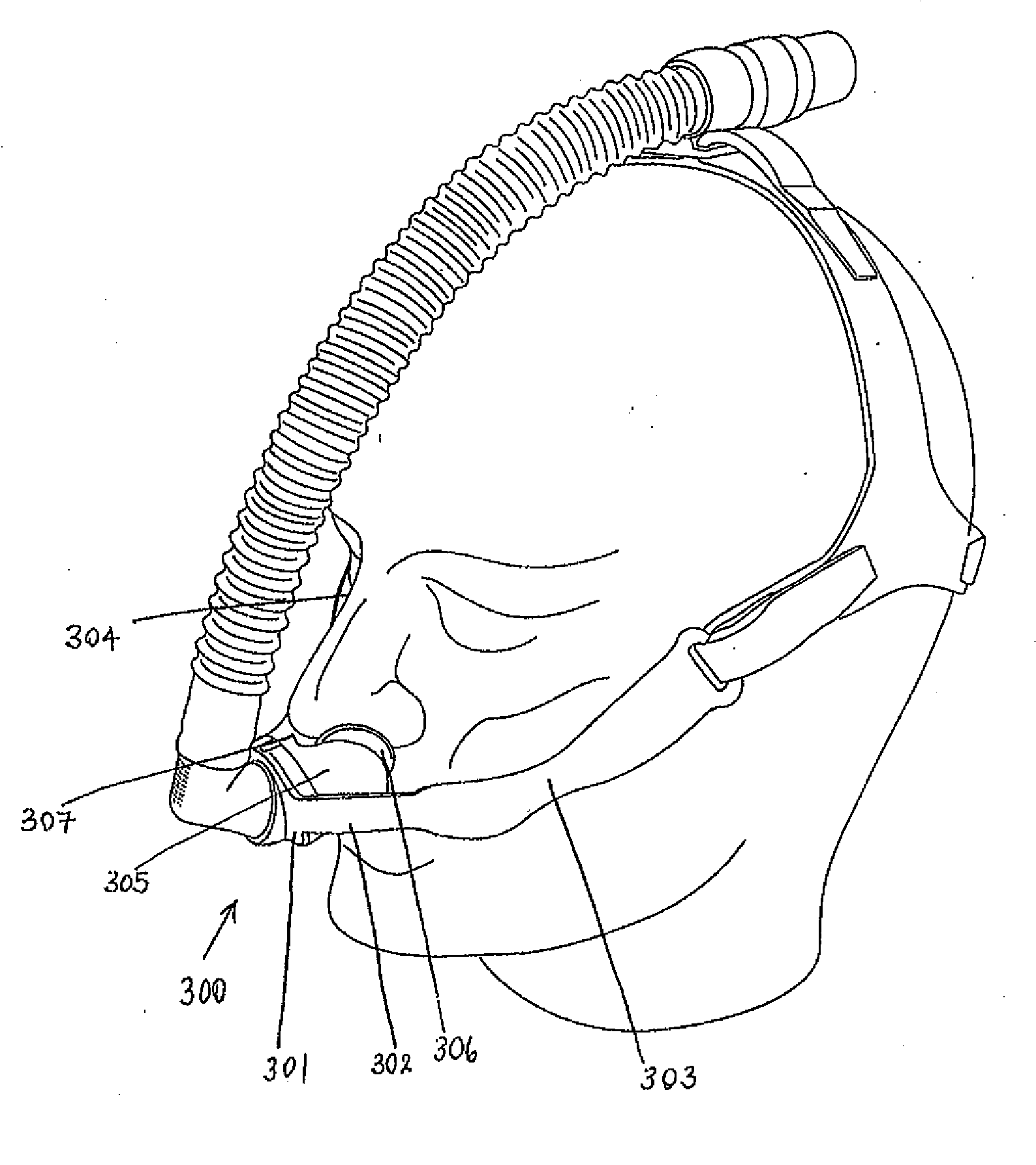
[0085]An example of this is shown in FIGS. 20 to 22, the patient interface and headgear 300. Here, the mask base 301 and the curved elongate member 302 are integrally formed, for example, by moulding or the like. The elongate member comprises arms 303, 304 similar to that described above. Also the mask body 305 has integral nasal pillows 306, 307 similar to that described above in relation to FIG. 2.

[0086]As can be seen in FIGS. 21 and 22 in this eighth embodiment the headgear straps 308, 309 do not extend down the arms 303, 304 as with other embodiments. In this embodiment the headgear straps 308, 309 attach through recesses 310, 313 at the end of the arms 303, 304 extending along the arms are inner pads 311, 312 that rest against the patients cheekbones in use and provide comfort to the patient's face. The pads 311, 312 only extend up to near the attachment recesses 309, 310. The pads are preferably made from a foam type material, such as the laminated material that the headgear s...

sixth embodiment

[0108]A seventh form of the patient interface and headgear of the present invention is shown in FIGS. 16 and 17. Here, the headgear and curved member is similar to that described above in the sixth embodiment, where the curved member 141 has a central section that curves under and anchors onto an inlet port 151 on a patient interface 150. The patient interface 150 is an integral mouth mask 152 and nasal pillows 153. The mouth mask 152 preferably extends under the user's 155 chin, as shown in FIG. 17.

[0109]The interface 150 has a substantially rigid body 154 that has substantially soft cushion 156 attached to it. The cushion 156 is preferably of the type disclosed in U.S. Pat. No. 6,951,218 (the entire contents of which is incorporated herein by reference) having an inner 157 and outer 158 cushions.

[0110]Integrally formed in the outer cushion 158 are nasal pillows 153. Preferably two nasal pillows 159, 160 are formed in the cushion 158. These are substantially tubular and carry gases...


PUM


Abstract

Headgear for use with a respiratory mask is described. The headgear includes a continuous and substantially curved elongate member extending in use below a user's nose and at least two headgear straps capable of attachment to the ends of the elongate member. A mask attachment on the elongate member is disposed to sit below or on one of said user's nose, mouth, upper lip and an inlet to the mask. The attachment is capable of receiving the mask.

Description

[0001]This application is a continuation of U.S. patent application Ser. No. 12 / 307,993, entitled “Breathing Assistance Apparatus” which has a filing date of Jan. 8, 2009, which is a National Phase application of PCT / NZ2007 / 000185 having an international filing date of Jul. 13, 2007, and which claims priority of New Zealand Patent Nos. 548575, filed on Jul. 14, 2006 and 551103, filed on Nov. 6, 2006, all of which are hereby incorporated by reference in their entirety.BACKGROUND OF THE INVENTION[0002]1. Technical Field[0003]The present invention relates to apparatus for treating sleep apnoea. More specifically, the present invention provides a nasal interface for the supply of respiratory gases, but most particularly positive pressure gases.[0004]2. Summary of the Prior Art[0005]In the art of respiration devices, a variety of respiratory masks which cover the nose and / or mouth of a human user in order to provide a continuous seal around the nasal and / or oral areas of the face are wel...

Claims


Application Information

Patent Timeline
IPC IPC(8): A61M16/06A62B18/02
CPCA61M16/06A61M16/0666A61M16/0683A61M16/16A61M2016/0039A61M2205/3368A61M16/161A61M2205/50A61M2210/0618A61M2210/0625A61M16/0611A61M16/0616A61M16/0825A61M2205/3653A61M16/024A61M16/0816A61M16/0622A61M16/0057A61M2205/0216
Inventor MCAULEY, ALASTAIR EDWINGLEESON, OLIVERERSTICH, EVAN STUARTFREEMAN, SIMON ERICDAVIES, NEIL GLENSCHOENBERG, STEPHEN JOHNLAW, KAMMANPRENTICE, CRAIG ROBERT
Owner FISHER & PAYKEL HEALTHCARE LTD
Learn More