Controlling Apparatus of Variable Capacity Type Fuel Pump and Fuel Supply System
a control apparatus and variable capacity technology, applied in the direction of fuel injecting pumps, electric control, machines/engines, etc., can solve the problems of difficult to change the drive timing, noisy, and inability to keep a common rail pressure at the desired pressure,
- Summary
- Abstract
- Description
- Claims
- Application Information
AI Technical Summary
Benefits of technology
Problems solved by technology
Method used
Image
Examples
embodiment 1
[0033]Hereinafter, explanation will be given about an embodiment of the present invention.
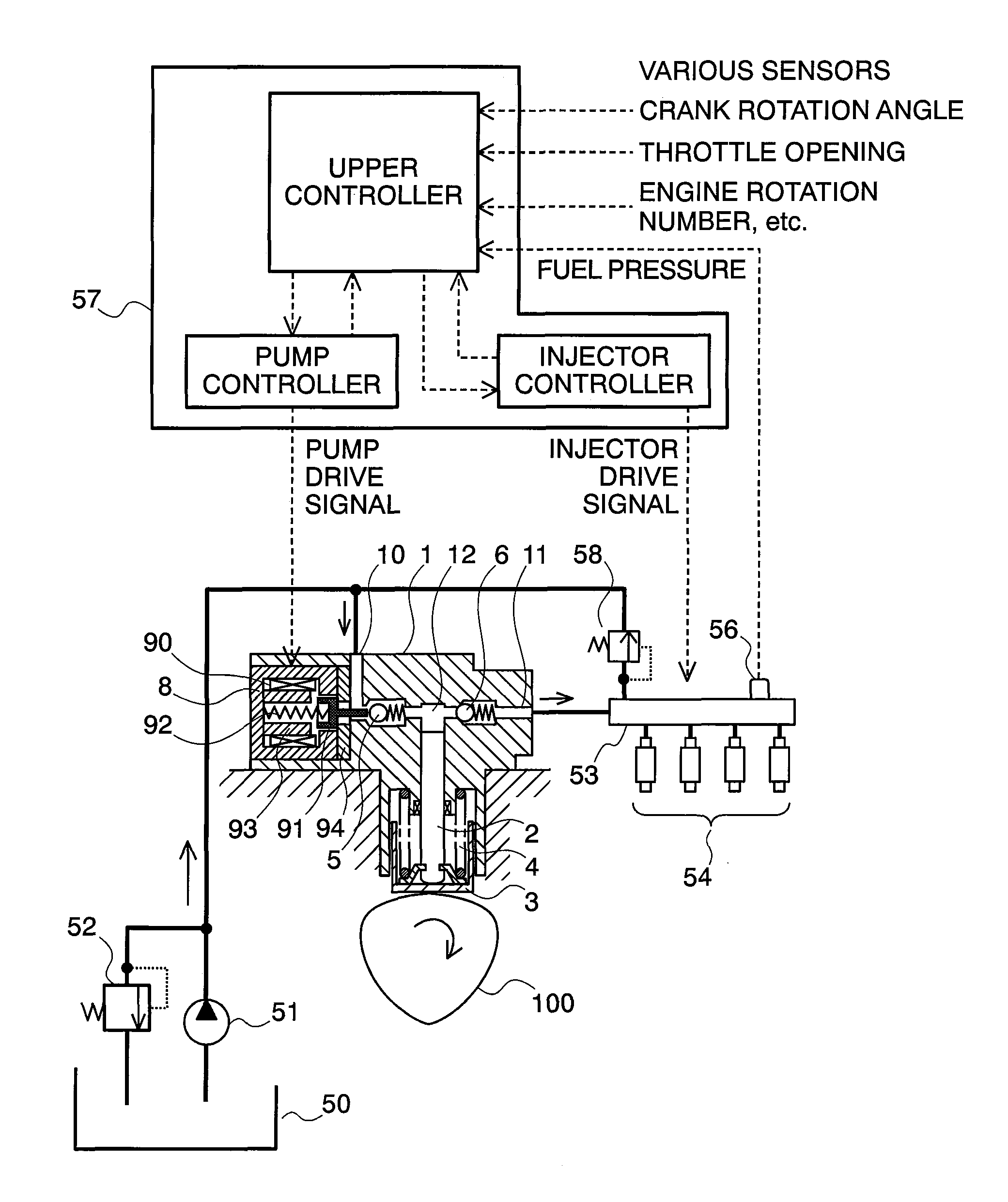
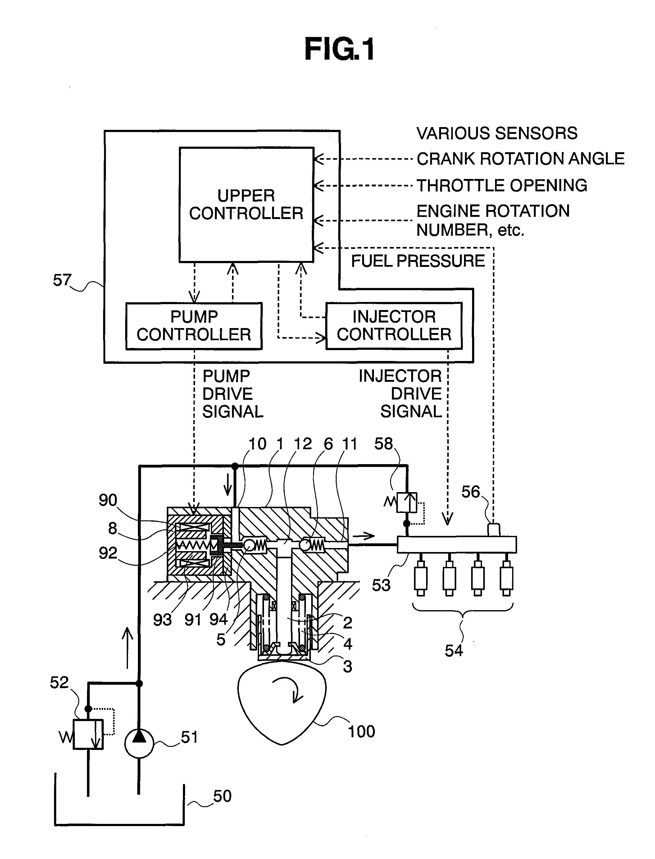
[0034]First of all, explanation will be made on the structures of a fuel supply system, which applies the variable capacity type fuel pump according to the present embodiment therein, by referring to FIG. 1. In a pump main body 1 are formed a fuel suction passage 10, a discharge passage 11, and a pressurizing chamber 12. Within the pressurizing chamber 12, a plunger 2 is slidably held and functions as a pressurizing member. In the suction passage 10 and the discharge passage 11 are provided a suction valve 5 and a discharge valve 6, respectively. The suction valve 5 and the discharge valve 6 are biased by springs in one direction, so that they act as a check valve. Also, to the suction passage 10 is connected a low-pressure valve 9.
[0035]A variable capacity control mechanism 8 is held within the pump main body 1, and is comprised of a solenoid coil 90, a rod 91, and a spring 92. The rod 91 is b...
embodiment 2
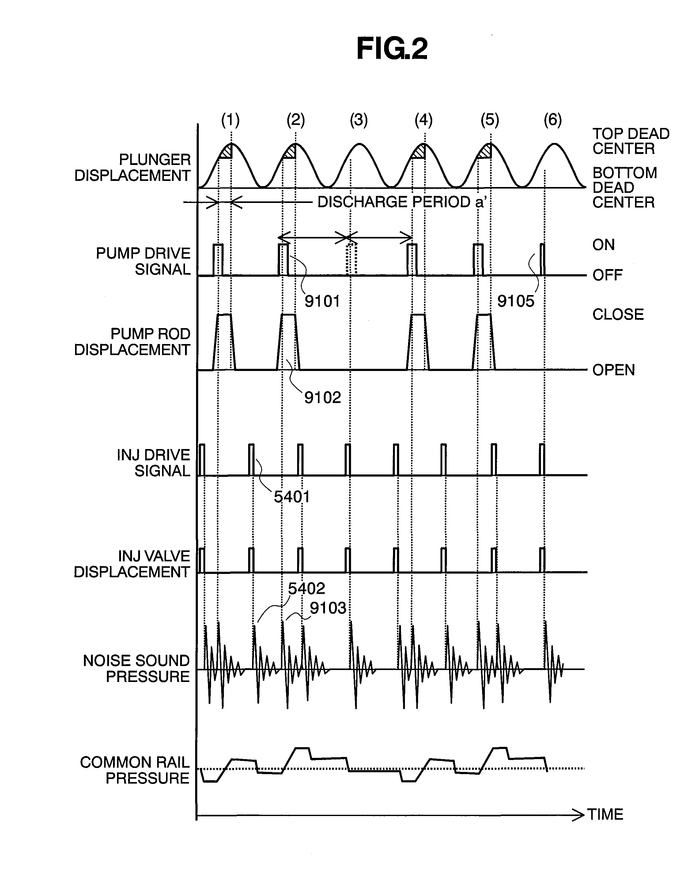
[0073]FIG. 6 shows a timing chart according to other embodiment of the present invention. The structures of the fuel supply system are similar to those of the system shown in FIG. 1.
[0074]For avoiding the noises of the pump and the injectors from overlapping on each other within the plunger cycle (3), the timing is moved forward when supplying the pump drive signal. With the pump building up, the flow rate is increased, being discharged from, when the drive timing thereof is moved forward. Accordingly, if only forward moving is made on the timing when the pump drive signal is provided for avoiding the overlapping of the noises, then the pump discharges the fuel much more than that of the desired discharge flow rate, thereby bringing about an increase of the fuel pressure within the common rail 53.
[0075]However, if reducing the flow rate discharged by shifting the timing of providing the pump drive signal backward, within the plunger cycles (1) or (2), so as to cancel the fuel discha...
embodiment 3
[0077]FIG. 7 shows a view of other embodiment.
[0078]A fuel pump 1a repeats the suction / discharge of fuel by reciprocating movement of a plunger 2a, and also controls a flow-amount control mechanism 8a, thereby controlling an amount of fuel to be discharged to a high-pressure side. The flow-amount control mechanism 8a is built up with a suction valve 5a and a rod 91a, in one body, and is biased into a direction to open the valve by way of a spring 92a. When no drive signal is provided to the flow-amount control mechanism 8a, the suction valve 5a is held closing the valve, through the biasing force of the spring 92a; therefore, the fuel pump 1a does not pressurize the fuel therein. When the drive signal is provided from the controller 57a, the suction valve 5a is biased towards the closing position of valve through magnetic sucking force, then it pressurizes the fuel within a pump chamber 12a.
[0079]The control method for the system of FIG. 7 is similar to that for the above-mentioned...
PUM
 Abstract
Description
Claims
Application Information
 - R&D
- Intellectual Property
- Life Sciences
- Materials
- Tech Scout
- Unparalleled Data Quality
- Higher Quality Content
- 60% Fewer Hallucinations
Browse by: Latest US Patents, China's latest patents, Technical Efficacy Thesaurus, Application Domain, Technology Topic, Popular Technical Reports.
© 2025 PatSnap. All rights reserved.Legal|Privacy policy|Modern Slavery Act Transparency Statement|Sitemap|About US| Contact US: help@patsnap.com


