
Glass-coated light-emitting element, light-emitting element-attached wiring board, method for producing light-emitting element-attached wiring board, lighting device and projector

a technology of light-emitting elements and wiring boards, which is applied in the direction of semiconductor devices, solid-state devices, color televisions, etc., can solve the problems of insufficient resolution of the above-mentioned problems, insufficient radiation intensity distribution, so as to increase the amount of utilizable light, the effect of increasing the directivity

Inactive Publication Date: 2009-09-24
ASAHI GLASS CO LTD
View PDF8 Cites 10 Cited by
  • Summary
  • Abstract
  • Description
  • Claims
  • Application Information

AI Technical Summary

Benefits of technology

[0020]According to the invention, since the coating glass has a function similar to that of the above-mentioned lens or light pipe, the alignment as described above becomes unnecessary. Namely, conventionally, when directivity is increased by using a lens, a semiconductor light-emitting element (hereinafter also briefly referred to as a light-emitting element) and the lens has been required to be separately disposed. Accordingly, the alignment thereof has been necessary. However, in the invention, such alignment becomes unnecessary.
[0021]Further, in the case where there is a space between the light-emitting element and the lens, when outgoing light goes out from the light-emitting element to the space and enters from the space to the lens, a certain rate thereof reflects. Since the refractive index of the light-emitting element is high in many cases, the amount of utilizable light decreases due to these reflections in such a case. Compared to this, in the invention, there is no space between the glass having a lens function and the light-emitting element. Accordingly, such a problem does not occur.
[0022]Furthermore, when a coating of the light-emitting element has a well-known bullet shape, a part of light which enters a portion corresponding to a cylindrical portion of the bullet from the light-emitting element is refracted at a surface of the coating to outgo to an external space, resulting in failure to reach a portion corresponding to a hemispherical surface portion of the bullet. Compared to this, in the invention, since light directly enters the spherical glass from the light-emitting element, much of the light which enters a lower hemispherical portion of the spherical glass corresponding to the cylindrical portion of the bullet returns to an electrode surface again by total reflection, and a light path thereof is changed by scattering at that place, whereby the light reaches an upper hemispherical portion of the spherical glass. Thus, the amount of utilizable light can be increased.
[0023]In addition, when the light-emitting element having the rectangular light-emitting portion is used in an image projection apparatus such as a TV or a projector, the light-emitting portion has the same shape as that of matter to be projected. Accordingly, lighting efficiency is improved. Further, application thereof to the projector causes an advantage that a LCD (liquid crystal display) becomes unnecessary.

Problems solved by technology

On the other hand, it is necessary to efficiently introduce outgoing light into a light control unit such as a liquid crystal panel or a micromirror array, because the outgoing light from the LED is non-directional.
However, such a conventional lens-attached light-emitting element comprises a set of three parts, a light-emitting element, a lens and a holder therefor, and a process for adjusting and fixing those parts is also necessary, resulting in high cost.
Further, there is also a problem that the radiation intensity distribution does not necessarily become efficient when the lens having a normal shape is used.
However, since alignment of the light pipe with the light-emitting element or the light control unit is also necessary, the resolution of the above-mentioned problems has been insufficient.

Method used


Image

  • Glass-coated light-emitting element, light-emitting element-attached wiring board, method for producing light-emitting element-attached wiring board, lighting device and projector
  • Glass-coated light-emitting element, light-emitting element-attached wiring board, method for producing light-emitting element-attached wiring board, lighting device and projector
  • Glass-coated light-emitting element, light-emitting element-attached wiring board, method for producing light-emitting element-attached wiring board, lighting device and projector

Examples


Embodiment Construction

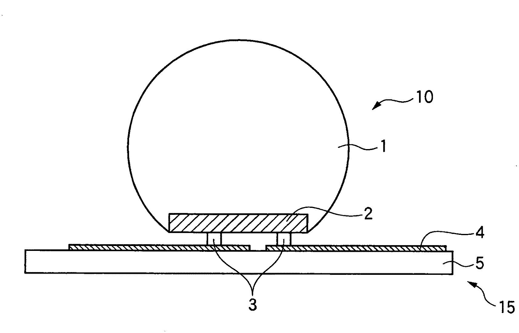
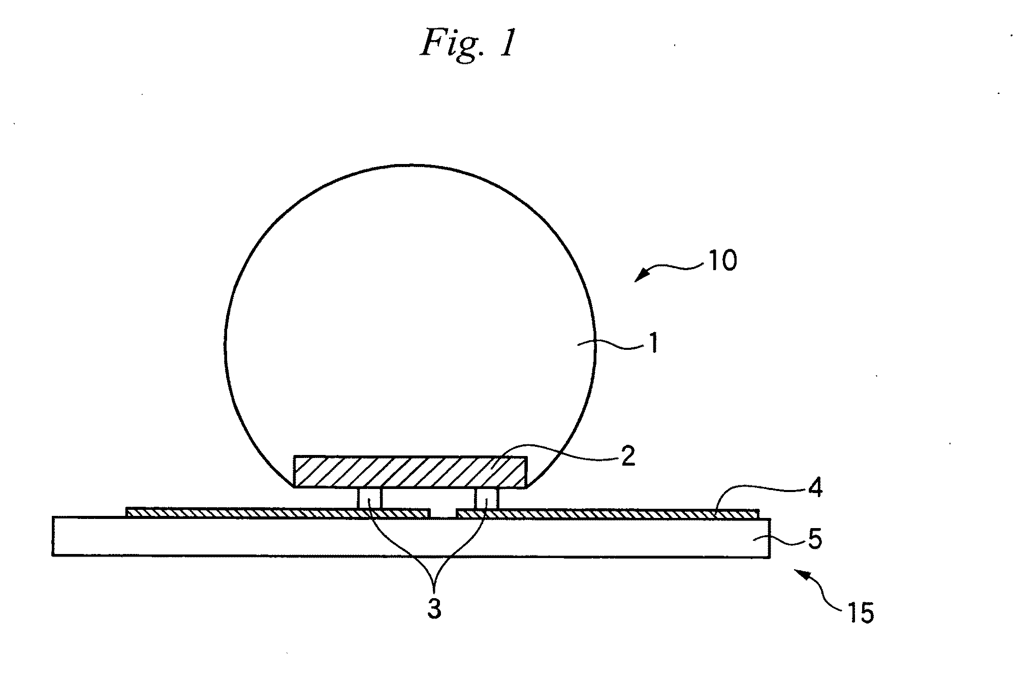
[0059]The glass-coated light-emitting element and light-emitting element-attached wiring board of the invention will be described below with reference to FIG. 1, but the invention is not limited to FIG. 1.

[0060]The reference numeral 2 indicates a light-emitting element, and electrodes (not shown) are formed on a lower surface thereof. As the light-emitting element 2, a LED or a laser diode may be mentioned, and a blue LED is typical. The light-emitting element 2 is generally rectangular or square, seen from above. Accordingly, the surface of a glass-coated light-emitting element 10 on which the electrodes are formed is also generally rectangular or square. When the light-emitting element 2 is rectangular or square, the maximum diameter L thereof is the diagonal length, and L is typically 400 to 1,500 μm.

[0061]The electrode which is a light-emitting surface of the light-emitting element 2 is not limited, and has, for example, an L shape (see FIG. 11). However, in the third light-emit...


PUM


Abstract

A glass-coated light-emitting element 10 of the invention has a semiconductor light-emitting element 2 having a surface on which no electrode is formed is coated with a glass 1, in which a surface of the glass 1 constitutes a part of a spherical surface broader than a hemispherical surface, the refractive index of the glass 1 at an emission peak wavelength of the semiconductor light-emitting element 2 is 1.7 or more, and the ratio of the diameter of the above-mentioned spherical surface to the maximum diameter of a surface of the semiconductor light-emitting element 2 on which electrodes are formed is 1.8 to 3.5, whereby light emitted from the light-emitting element can be efficiently introduced into a light control unit, and alignment with a lens or a light pipe, which has hitherto been made, becomes unnecessary.

Description

CLAIM OF PRIORITY[0001]This application claims priority to Japanese Patent Application No. 2006-274017, filed on Oct. 5, 2006, Japanese Patent Application No. 2006-301558, filed on Nov. 7, 2006, Japanese Patent Application No. 2007-110331, filed on Apr. 19, 2007, and International Application No. PCT / JP2007 / 069623, filed on Oct. 5, 2007. Each of these applications is incorporated herein in its entirety by reference.TECHNICAL FIELD[0002]The present invention relates to a semiconductor light-emitting element coated with glass, a lighting device and a projector.BACKGROUND ART[0003]Semiconductor light-emitting elements represented by light-emitting diodes (LEDs) have characteristics of small size, high efficiency and long life, and have been used in various applications.[0004]For example, when the LED is used as a projector light source, a lighting system can be made compact because of its small size. On the other hand, it is necessary to efficiently introduce outgoing light into a ligh...

Claims


Application Information

Patent Timeline
Patent Type & Authority Applications(United States)
IPC IPC(8): H01L33/00H01L33/54H01L33/56
CPCH01L33/54H01L2224/13H04N9/315H01L33/56
Inventor NAKAMURA, NOBUHIROSEKINE, MINORUMATSUMOTO, SYUJI
Owner ASAHI GLASS CO LTD
Learn More