
Gas diffusion layer in a fuel cell

a technology of gas diffusion layer and fuel cell, which is applied in the field of fuel cell, can solve the problem that the efficiency of the diffusion of reactant gases in the gas channel cannot be sufficiently enhanced, and achieve the effect of improving the diffusion efficiency of reactant gases

Active Publication Date: 2009-09-24
TOYOTA JIDOSHA KK +1
View PDF8 Cites 15 Cited by
  • Summary
  • Abstract
  • Description
  • Claims
  • Application Information

AI Technical Summary

Benefits of technology

[0008]In view of the aforementioned circumstances, it is an object of the invention to provide a fuel cell intended to improve the diffusion efficiency of a reactant gas in a gas channel.

Problems solved by technology

Therefore, there is a problem of the efficiency of the diffusion of the reactant gases in the gas channels cannot be sufficiently heightened.

Method used


Image

  • Gas diffusion layer in a fuel cell
  • Gas diffusion layer in a fuel cell
  • Gas diffusion layer in a fuel cell

Examples


Embodiment Construction

[0034]In the following description and the accompanying drawings, the present invention will be described in more detail with reference to exemplary embodiments.

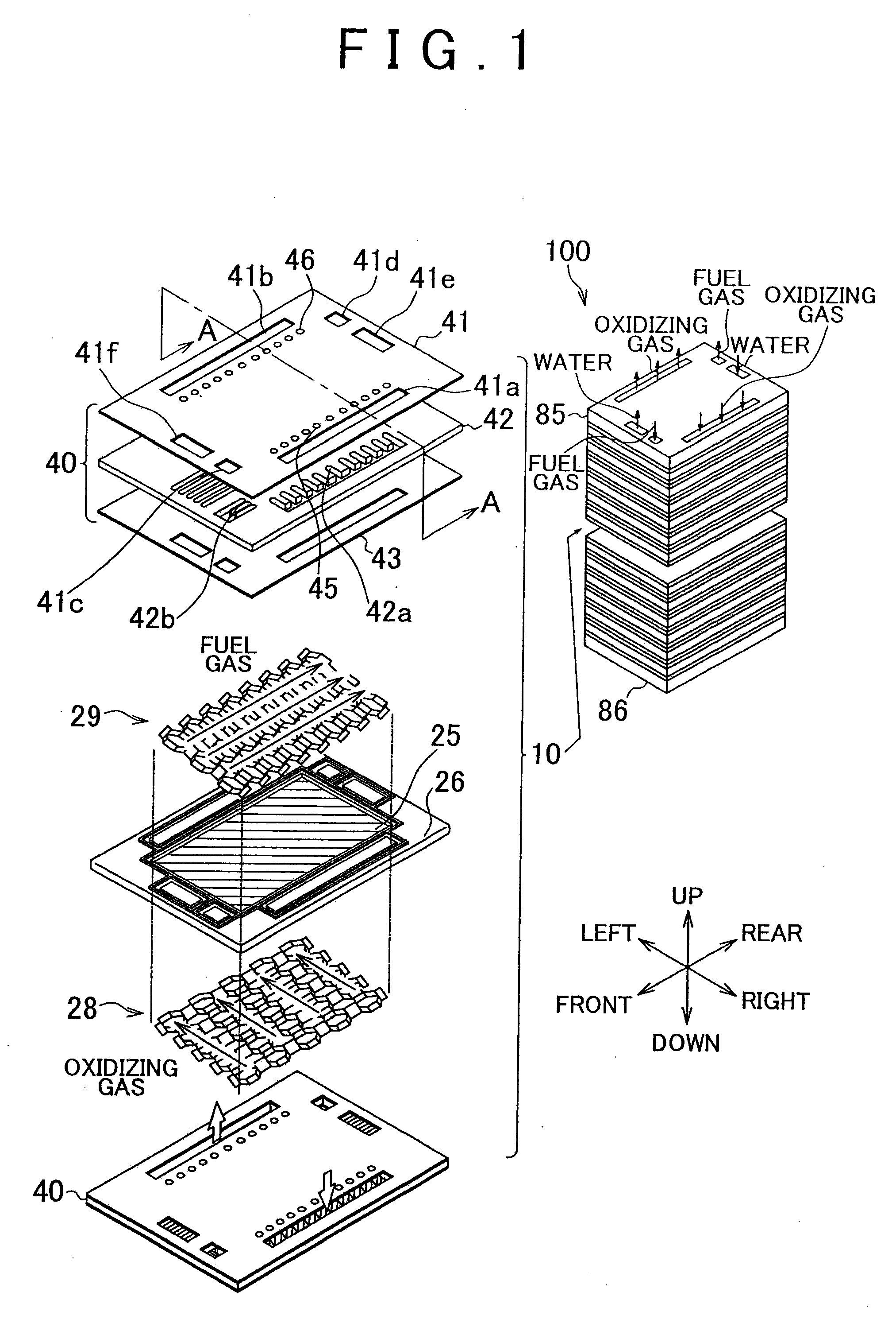
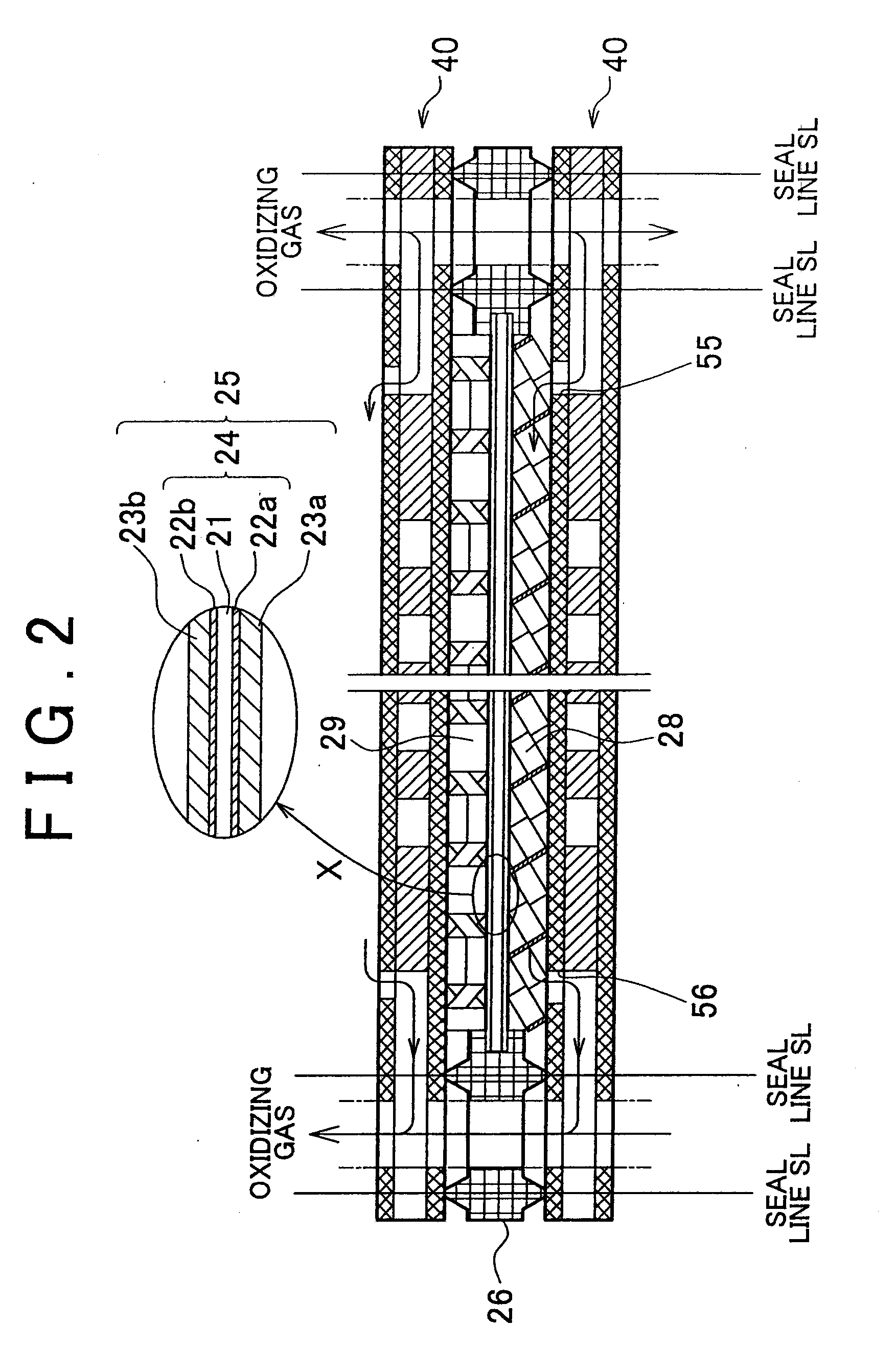
[0035]Firstly, an overall construction of a fuel battery will be described. FIG. 1 is an illustrative diagram showing an overall construction of a fuel battery 100 in an embodiment of the invention. FIG. 2 is a sectional view of one of fuel battery cells 10 that constitute the fuel battery 100 taken on a plane A-A of FIG. 1. The fuel battery 100 of this embodiment is a solid polymer type fuel battery that is supplied with a fuel gas containing hydrogen and an oxidizing gas containing oxygen, and that generates electricity through electrochemical reactions between the fuel gas and the oxidizing gas (hereinafter, collectively referred to as “the reactant gases” when needed).

[0036]As shown in FIG. 1, in the fuel battery 100, a plurality of fuel battery cells 10 are stacked, and are clamped on both ends by end plates 85, 86. Eac...


PUM

PropertyMeasurementUnit
porosityaaaaaaaaaa
lengthaaaaaaaaaa
lateral widthaaaaaaaaaa

Abstract

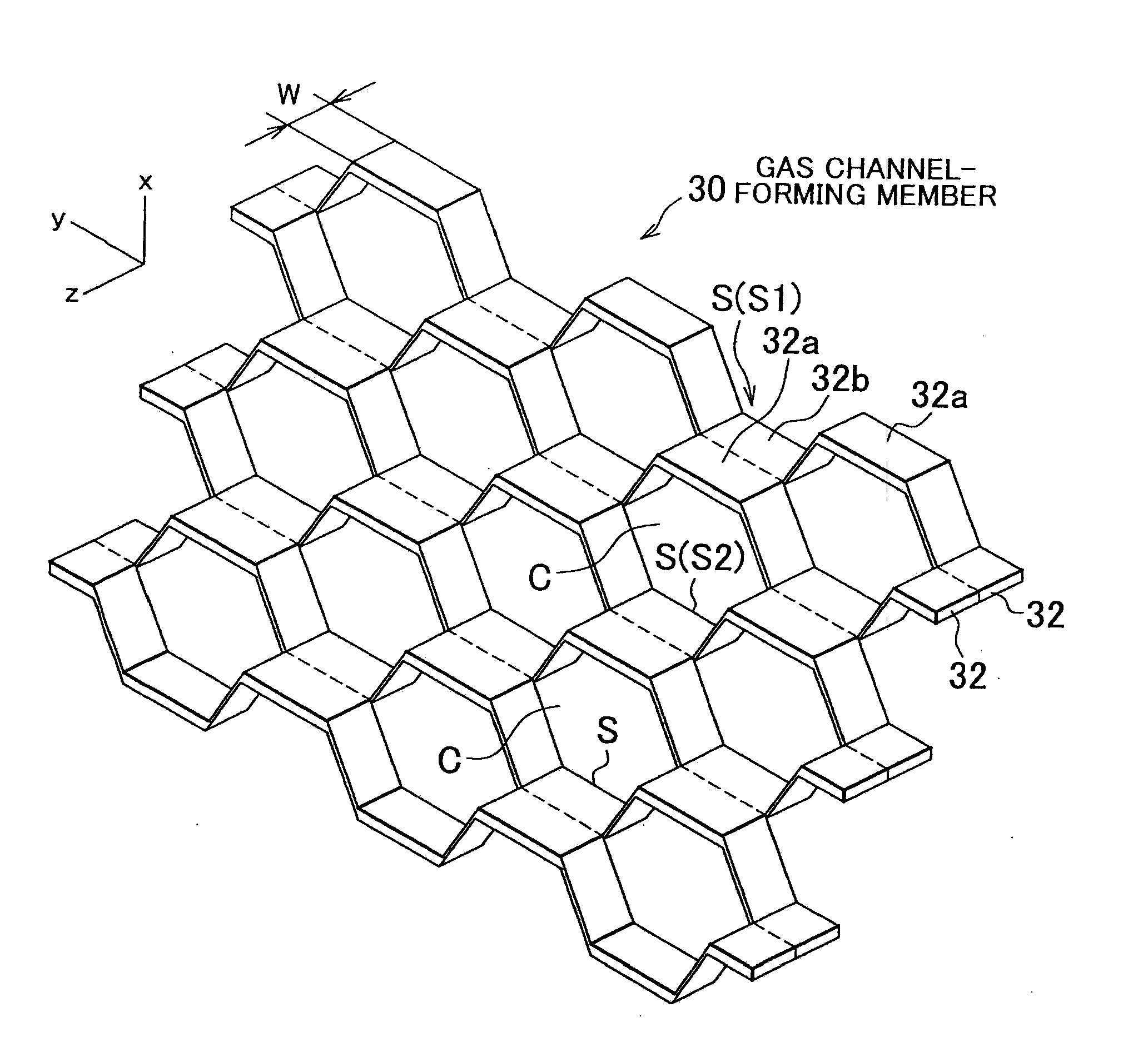
A fuel cell includes a gas channel-forming member that forms a channel for supplying a reactant gas to a plane of an electrode. A basic structure of the gas channel-forming member is a corrugated plate portion in which ridge portions and trough portions continuously alternate with each other. In the gas channel-forming member, a plurality of corrugated plate portions are interconnected. Specifically, two adjacent corrugated plate portions are interconnected so that the trough portions of one of the two connect to the ridge portions of the other corrugated plate portion. The gas channel-forming member is disposed so that the direction of alignment of the connection planes S formed by the interconnection between the trough portions and the ridge portions is parallel to the plane of the electrode. This structure improves the diffusion efficiency of the reactant gas in the gas channel.

Description

BACKGROUND OF THE INVENTION[0001]1. Field of the Invention[0002]The invention relates to a fuel cell that has gas channel-forming members.[0003]2. Description of the Related Art[0004]In recent years, fuel cells that generate power through electrochemical reactions between a hydrogen gas and oxygen have been drawing attention as an energy source. A fuel battery has a structure that is formed by stacking a plurality of cells each of which is constructed by integrating a membrane-electrode assembly made up of an electrolyte membrane and electrode catalyst layers formed thereon, separators, and gas channels disposed between the membrane-electrode assembly and the separators. The gas channels feed the reactant gases that are used for electric power generation of the fuel battery, for example, a hydrogen gas, or an oxidizing gas, into the membrane-electrode assemblies.[0005]Japanese Patent Application Publication No. 2005-310633 (JP-A-2005-310633) proposes a construction that employs an e...

Claims


Application Information

Patent Timeline
Patent Type & Authority Applications(United States)
IPC IPC(8): H01M8/10
CPCH01M8/0247H01M8/0258Y02E60/50Y02E60/523H01M2008/1095H01M8/2483H01M8/241H01M8/0267H01M8/2457H01M8/026Y02P70/50
Inventor MOTEKI, KAZUNARI
Owner TOYOTA JIDOSHA KK
Learn More