Ball pivot

a technology of ball pivot and pivoting rod, which is applied in the direction of mechanical equipment, couplings, transportation and packaging, etc., can solve the problems of not ensuring that the magnetic field-sensitive sensor has “sufficient field” and may suffer special drawbacks

Inactive Publication Date: 2009-09-24
ZF FRIEDRICHSHAFEN AG
View PDF19 Cites 13 Cited by
  • Summary
  • Abstract
  • Description
  • Claims
  • Application Information

AI Technical Summary

Benefits of technology

[0006]Based on this state of the art, the basic object of the present invention is to provide a ball pivot, which is suitable for mass production and in which a magnet is securely mounted. Furthermore, an adverse effect of the magnetic field generated by the magnet concerning measurement of that magnetic field by means of a magnetic field-sensitive sensor shall be avoided even if a ferromagnetic material is used for the ball pivot.
[0011]Due to the fact that the intermediate space formed between the jacket surface of the magnet and the inner wall of the recess is filled with a nonmagnetic material, the magnet, designed especially as a permanent magnet, can be mounted in the ball pivot in a reliable process within the framework of mass production. Furthermore, the adverse effect on the magnetic field generated by the magnet concerning a measurement of this magnetic field by means of a magnetic field-sensitive sensor, which is arranged especially outside the ball pivot, is reduced by the arrangement of the nonmagnetic material around the magnet in the intermediate space especially if the ball pivot is made of a ferromagnetic material. The shape of the magnetic field generated by the nonmagnetic material, which shape is more favorable for the magnetic field measurement, makes possible the more reliable and more accurate determination of the position of the magnet by means of this magnetic field measurement. It is also possible to compensate differences in the thermal expansion characteristics of the magnet and the ball pivot in case of thermal shock stresses by suitably selecting the nonmagnetic material.
[0017]Furthermore, self-centering of the ring becomes possible in the recess by the adhesive, and the use of a partially elastic adhesive also guarantees reliable connection for the case in which strong thermal shock stresses develop. Such an adhesive can compensate the differences in the coefficients of thermal expansion of the ring and the ball pivot. For example, a UV-curing adhesive can be used as an adhesive if the ring is made of a material that is transparent to UV light. If the ring is made of plastic, the ring may also be injection molded directly into the recess having the magnet according to an alternative.

Problems solved by technology

The arrangement of the magnet in the ball pivot is not described sufficiently in the above-mentioned documents, so that drawbacks may arise especially in the manufacturing process.
Thermal shock stresses may also lead to problems in case of insufficient fastening of the magnet in the ball pivot.
Furthermore, ball pivots for motor vehicles are regularly manufactured from a ferromagnetic material, which may adversely affect the shape of the magnetic field generated by the magnet concerning a measurement of this magnetic field.
It is possible, in particular, that the magnetic flux takes place decisively in the ferromagnetic material and it is not ensured that “sufficient field” is available to the magnetic field-sensitive sensor.

Method used


Image

  • Ball pivot
  • Ball pivot
  • Ball pivot

Examples


first embodiment

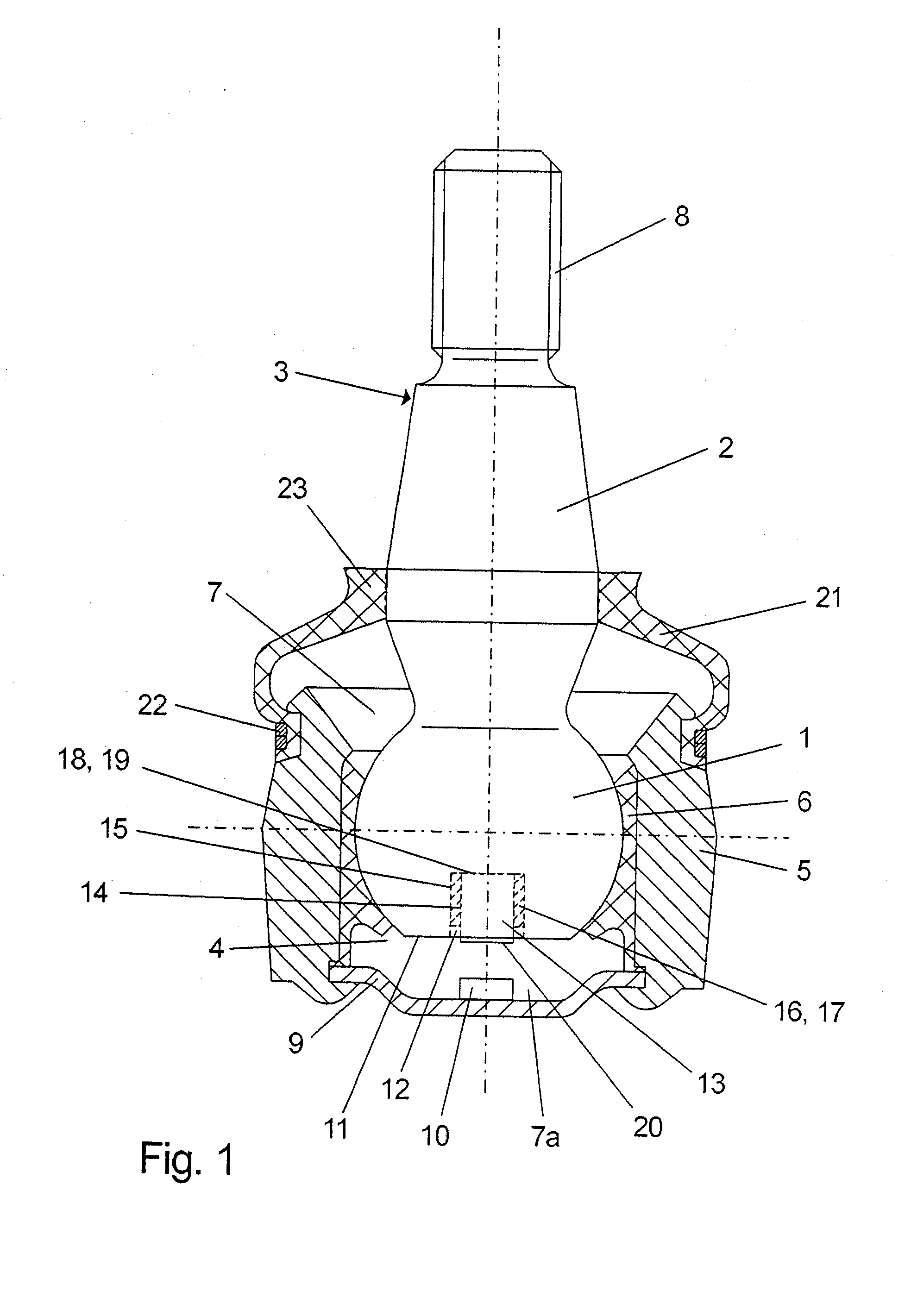
[0040]FIG. 2 shows the ball pivot 3 according to the present invention, in which a ring 24 made of plastic is bonded together with a magnet 13 into a recess 12 of the ball pivot 3 and the magnet 13 is in contact by its front side 18 facing the ball pivot 3 with the bottom surface 19 of the recess 12. The plastic used is transparent to UV light, and the adhesive cures on exposure to UV light, which is especially favorable for mass use. There is no gap between the ring 24 and the pivot 3, so that a possible focus of corrosion is ruled out.

second embodiment

[0041]FIG. 3 shows the ball pivot 3 according to the present invention, in which a cylindrical magnet 13 is completely embedded in a plastic element 25 manufactured according to the injection molding method. The body formed by the magnet 13 and the plastic element 25 is pressed into a recess 12 of the ball pivot 3, and the magnet 13 is in contact with the bottom surface 19 of the recess 12 by its front side 18 facing the ball pivot 3, so that, on the whole, a robust component is created in a simple mounting process. Because of the pressing in, the use of an adhesive can be eliminated, so that no dripping and drying times of a UV-curing adhesive need to the taken into account.

third embodiment

[0042]FIG. 4 shows the ball pivot 3 according to the present invention, in which a truncated cone-shaped magnet 13 is completely embedded in a plastic element 25 manufactured according to the injection molding method. The magnet 13 is in contact with the bottom surface 19 of the recess 12 by its front side 18 facing the ball pivot 3 and tapers from the bottom surface 19 with increasing distance from the latter.


PUM


Abstract

A ball pivot (3) of a ball and socket joint for a motor vehicle, with a pivot (2) and with a joint ball (1) connected thereto. A recess (12) with a magnet (13) arranged therein is provided in the ball pivot (13). An intermediate space (17), which is filled with a nonmagnetic material (16) for fixing the magnet (13), is formed between the jacket surface (14) of the magnet (13) and the inner wall (15) of the recess (12).

Description

CROSS REFERENCE TO RELATED APPLICATIONS[0001]This is a continuation under 37 CFR 1.53(b) of pending prior application Serial No. 12 / 027,601 filed February 7, 2008, which is a divisional of Ser. No. 10 / 566,123 filed Jan. 25, 2006, which is a United States National Phase application of International Application PCT / DE 2004 / 001867 filed Aug. 23, 2004 and claims the benefit of priority under 35 U.S.C. § 119 of German Patent Application DE 103 41 466.5 filed Sep. 5, 2003, the entire contents of each of the applications are incorporated herein by reference.FIELD OF THE INVENTION[0002]The present invention pertains to a ball pivot of a ball and socket joint for a motor vehicle, with a pivot and with a joint ball connected to same, wherein a recess with a magnet arranged therein is provided in the ball pivot. The present invention pertains, furthermore, to a ball and socket joint with such a ball pivot.BACKGROUND OF THE INVENTION[0003]A ball and socket joint for a motor vehicle, in which a ...

Claims


Application Information

Patent Timeline
Patent Type & Authority Applications(United States)
IPC IPC(8): F16C11/00F16C11/06
CPCF16C11/0604F16C11/0642F16C11/0647Y10T403/32696Y10T403/32631Y10T403/32672B60G2204/416F16C2233/00B60G2204/11B60G2401/17F16C11/06
Inventor SPRATTE, JOACHIMKLANK, MICHAEL
Owner ZF FRIEDRICHSHAFEN AG
Why Eureka
Try Eureka