Image processing apparatus

a technology of image processing and image pickup, which is applied in the direction of exposure control, color signal processing circuit, instruments, etc., can solve the problems of total or partial overexposure, limited dynamic range of image pickup apparatus that acquires images by image pickup elements such as ccd (coupled charge device) and cmos (complementary metal oxide semiconductor) sensors, etc., to achieve accurate display, accurate display, and easy and accurate setting

Active Publication Date: 2009-09-17
ORMON CORP
View PDF5 Cites 14 Cited by
  • Summary
  • Abstract
  • Description
  • Claims
  • Application Information

AI Technical Summary

Benefits of technology

[0024]According to the present invention, the composite image data is displayed at the time of setting, and designation of the area to be accurately displayed or the important area such as the area to be inspected and measured is received, and therefore this area can be set easily and accurately. Also, during operating the image processing apparatus, this important area can be accurately displayed on a display apparatus of limited luminance gradation, or can be accurately inspected and measured by image processing for processing the image of limited luminance gradation. Although there is a possibility that an overexposure, an underexposure, or the like also occurs in the image other than the important area, the image of the important area which is a portion of the entire area to be photographed can be accurately generated, while holding general information of the entire area to be photographed, because the image of the entire area to be photographed expressed by a common luminance gradation conversion is obtained.

Problems solved by technology

Generally, a dynamic range (a gradation range capable of expressing luminance) of an image pickup apparatus that acquires images by an image pickup element such as a CCD (Coupled Charged Device) and a CMOS (Complementary Metal Oxide Semiconductor) sensor is limited.
Therefore, when an exposure amount at the time of photographing is increased, total or partial overexposure (halation) occurs in a photographed image, and luminance information and color information of the measuring object cannot be accurately acquired.
Reversely, when the exposure amount is decreased at the time of photographing, total or partial underexposure occurs, and therefore effective luminance information cannot be acquired.
Further, in the measuring object having a portion of locally different reflectance and the measuring object having irregularities like a mirror surface, partial overexposure or underexposure occurs under an influence of lighting.
Thus, a difference between a brightest portion and a darkest portion included in an image of the measuring object formed on the image pickup element is large, and when the dynamic range of the image to be obtained originally exceeds the dynamic range of the image pickup element, there arises a problem that the whole body of the measuring object cannot be properly photographed.
According to this aspect, the image of the area other than the important area can be easily generated during operation of the image processing apparatus, thus realizing uncomplicated processing.

Method used


Image

  • Image processing apparatus
  • Image processing apparatus
  • Image processing apparatus

Examples


first embodiment

Overall Apparatus Structure

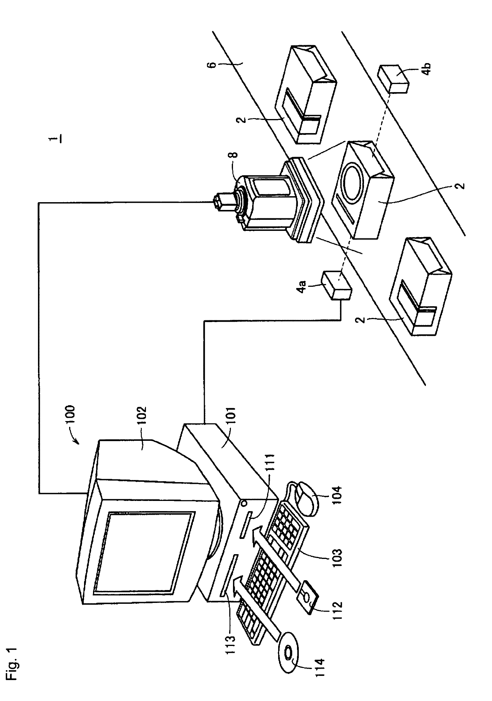
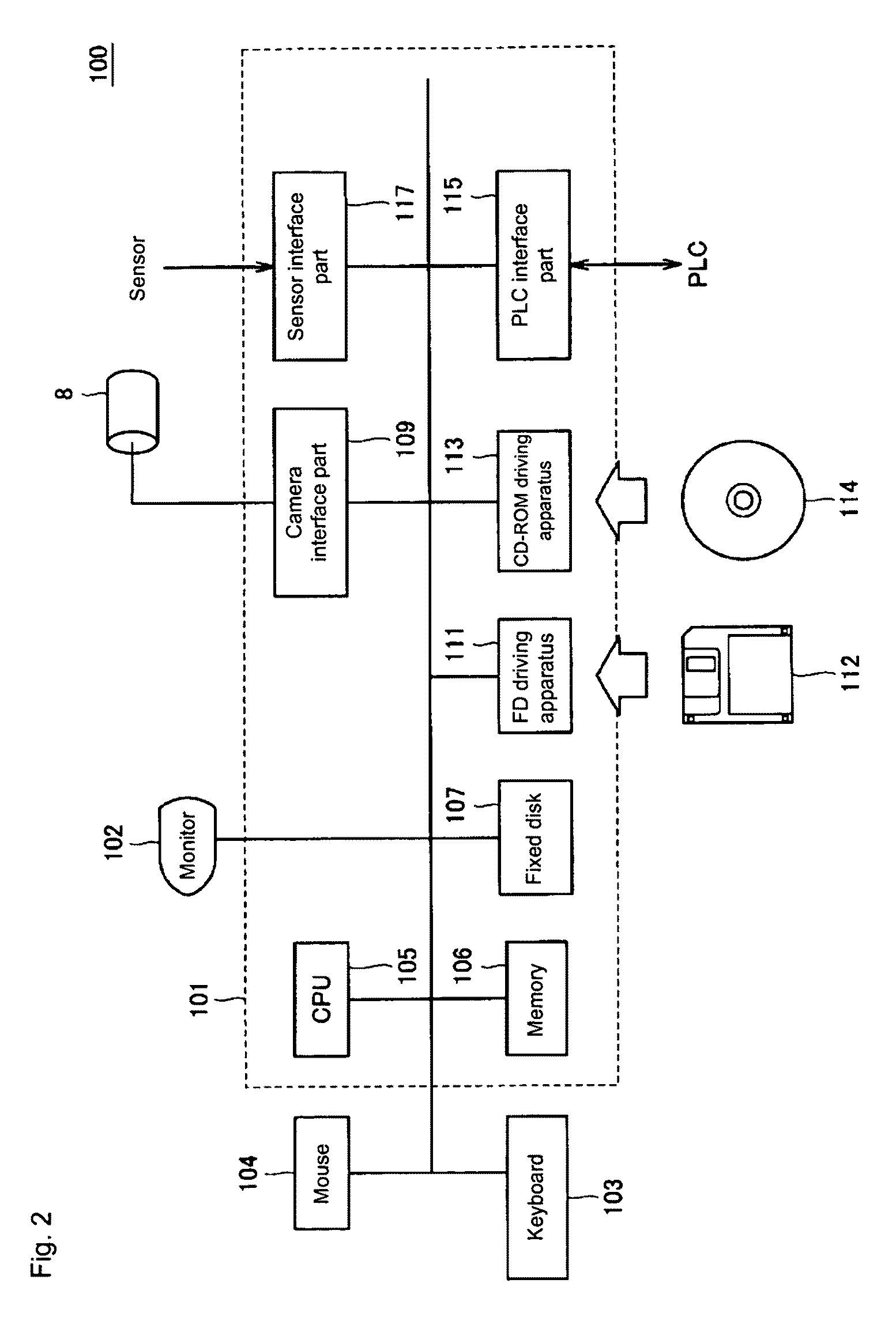
[0056]FIG. 1 shows a schematic view illustrating an overall structure of a visual sensor system 1 including an image processing apparatus according to a first embodiment of the present invention.

[0057]In FIG. 1, the visual sensor system 1 is typically incorporated in a production line and functions to optically inspect a defect and the like in a measuring object (referred to as a “workpiece” hereinafter) and optically measure its size and the like. As an example, in the first embodiment of the present invention, a workpiece 2 is conveyed by a conveying mechanism 6 such as a belt conveyor, and the conveyed workpiece 2 is sequentially photographed by an image pickup apparatus 8. The image data (referred to as “input image data” hereinafter) photographed by the image pickup part 8 is transmitted to a computer 100 that is a typical example of the image processing apparatus according to the present embodiment. Note that there may be further provided a lighting ...

second embodiment

[0240]When the user sets the photographing conditions in the setting mode, it is considered that in many cases, illumination or the like is adjusted through try and error, according to a conveying speed of the workpiece. In this case, when a moving amount (motion amount) per unit time of the workpiece is relatively large, the motion of the workpiece cannot be displayed unless the processing time required for generating the composite image data is shortened. Therefore, description will be given for a structure enabling setting of the photographing conditions while observing the motion of the measuring object, even by a user not having preliminary knowledge, as the image processing apparatus according to a second embodiment.

[0241]An overall structure of a visual sensor system 1 including the image processing apparatus according to the second embodiment of the present invention is the same as the structure of FIG. 1, and therefore detailed description is not repeated. Also, a hardware ...

third embodiment

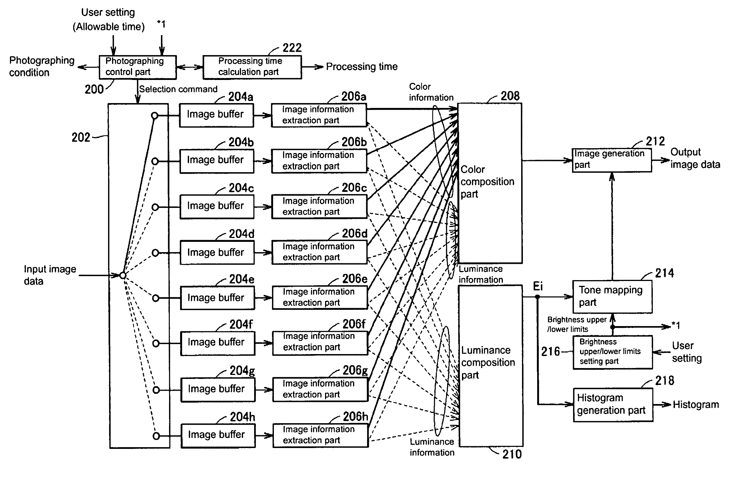
[0283]As described above, in the image composition processing according to the present invention, by using the luminance information and the color information of a plurality of input image data, the composite luminance information and the composite color information are calculated per pixel. Therefore, the time required for the image composition processing is proportional to the number of pixels and the number of input image data to be processed.

[0284]Meanwhile, the size of the workpiece to be inspected is small in many cases compared with the photographing range of the image pickup apparatus. In such a case, by performing image composition processing only for the pixel to be inspected, the processing time can be further shortened. Therefore, as the image processing apparatus according to the third embodiment, description will be given for a structure in which the image composition processing can be performed only for each pixel included in an area to be processed.

[0285]The overall ...


PUM


Abstract

When an area desired to be displayed with high accuracy and an area desired to be inspected and measured with high accuracy in a measuring object are smaller than a photographing range, the entire area of a composite image is displayed and designation of an area is received, to thereby generate an image of the entire area in which composition processing of optimizing luminance of pixels included in this area is performed. Therefore, an input part is provided for receiving the setting of a designated area in image data, a composite luminance distribution is calculated based on the size of a standardized luminance distribution value in the designated area, and composite image data is generated.

Description

BACKGROUND OF THE INVENTION[0001]1. Technical Field[0002]The present invention relates to an image processing apparatus capable of generating composite image data, in which a dynamic range is extended, by using a plurality of image data obtained by photographing a measuring object more than once based on different exposure conditions.[0003]2. Related Art[0004]In an FA (Factory Automation) field, a so-called visual sensor is put into practical use, as an apparatus for optically inspecting a defect and the like generated in a measuring object such as a workpiece, and optically measuring a size of this defect.[0005]When inspection and measurement are performed by using such a visual sensor, the measuring object must be properly photographed. Generally, a dynamic range (a gradation range capable of expressing luminance) of an image pickup apparatus that acquires images by an image pickup element such as a CCD (Coupled Charged Device) and a CMOS (Complementary Metal Oxide Semiconductor) ...

Claims


Application Information

Patent Timeline
Patent Type & Authority Applications(United States)
IPC IPC(8): H04N5/243G06T3/00H04N5/335H04N5/353H04N5/355
CPCH04N5/235H04N5/35536H04N5/2355H04N23/70H04N23/741H04N25/58
Inventor KATO, YUTAKA
Owner ORMON CORP
Why Eureka
Try Eureka