Methods and apparatus for a power supply

Active Publication Date: 2009-09-10
INFINEON TECH AUSTRIA AG
View PDF15 Cites 6 Cited by
  • Summary
  • Abstract
  • Description
  • Claims
  • Application Information

AI Technical Summary

Benefits of technology

[0005]Methods and apparatus for a power supply according various aspects of the present invention operate in conjunction with a voltage converter for converting an input voltage to an output voltage. For example, the converter may comprise an output controller configured to generate a control signal, a power mode controller, and an integrated power stage. The power stage may include a multiple switch segments coupled in parallel between the

Problems solved by technology

For high power applications, the active components are discrete, not integrated, because of the difficulty associated with integrating high power components and controlling heat dissipation.
Switching power supplies have a number of problems associated with them.
These MOSFETs are significantly larger than typical MOSFETs, and have high parasitic capacitances associated with them, which reduce the overall performance of the system.
If the drivers are not well controlled, unnecessary capacitive switching losses are introduced into the system.
Switching the power MOSFETs on and off also requires large currents, which create a significant amount of system noise through coupling and ground return path parasites.
The large currents provided to the MOSFETs also create a drop in the power supply, preventing the MOSFETs from turning on completely until the power supply has recovered.
In addition, the MOSFETs are timed to ensure that one is fully off before the other turns on, creating a large non-overlap time and causing losses to power efficiency.
In discrete power stages, the non-overlap time can be significant, causing loss in power efficiency because the output current must be provided by a diode during the non-overlap time.

Method used


Image

  • Methods and apparatus for a power supply
  • Methods and apparatus for a power supply
  • Methods and apparatus for a power supply

Examples


Embodiment Construction

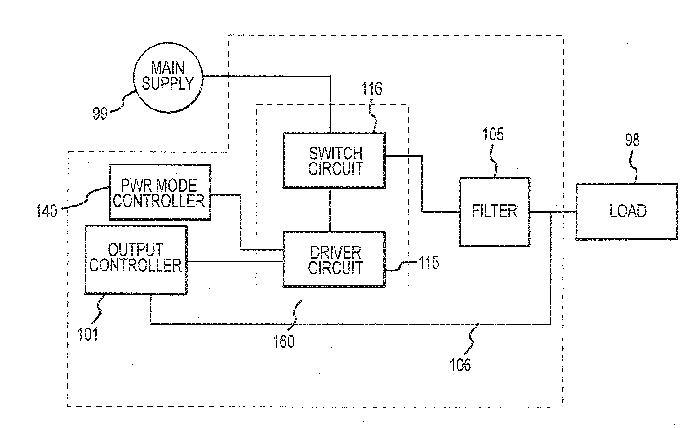
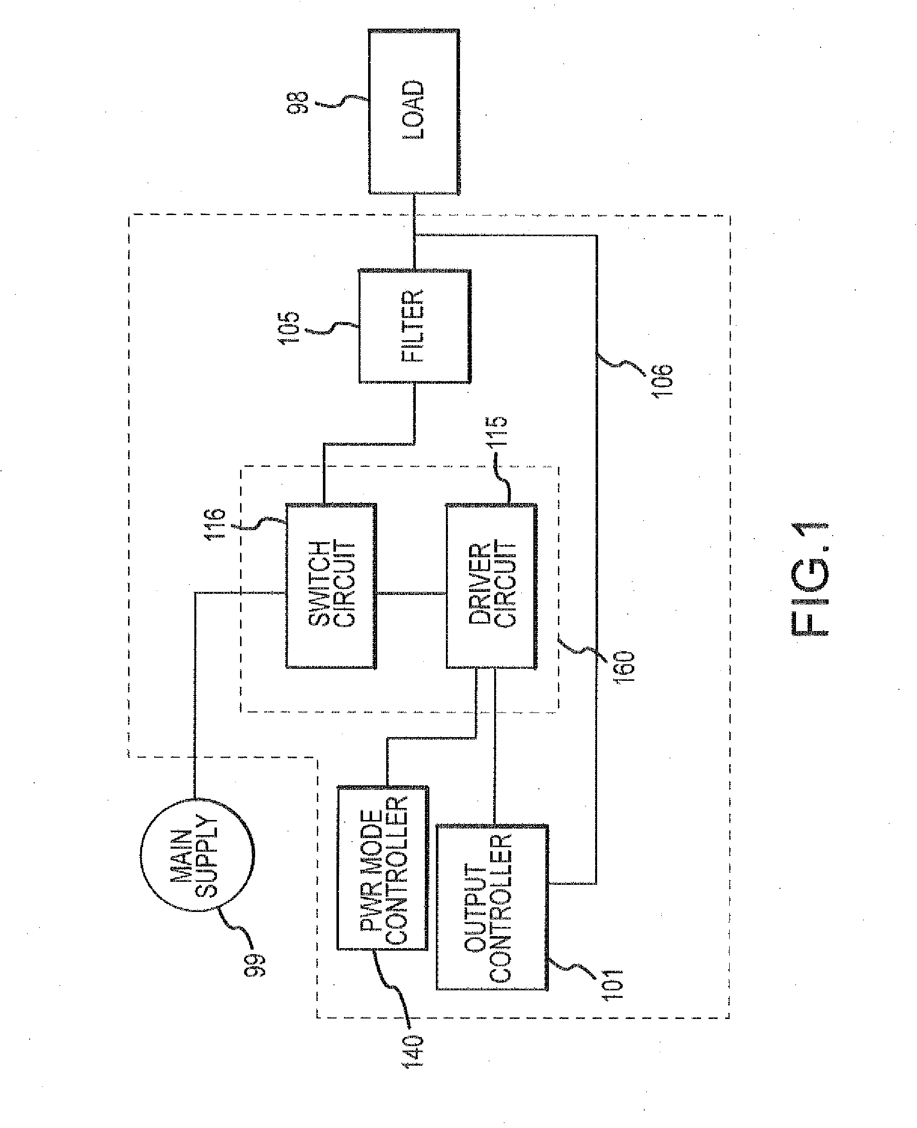
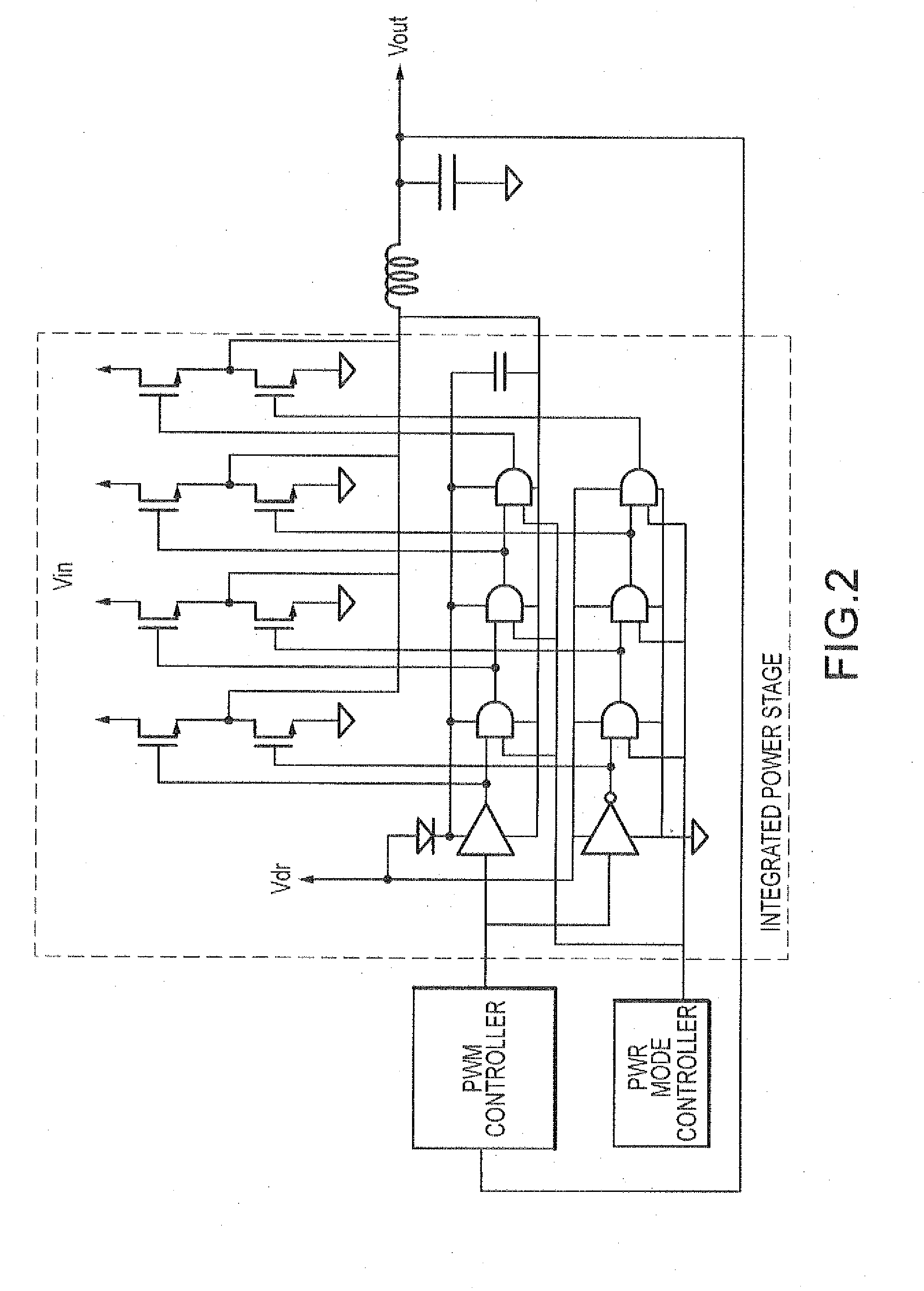
[0011]The present invention may be described in terms of functional block components and various processing steps. Such functional blocks may be realized by any number of hardware or software components configured to perform the specified functions and achieve the various results. For example, the present invention may employ various switches that may be implemented in any appropriate manner, such as using field effect transistors, diodes, latches, bipolar transistors, and the like, which may carry out a variety of functions. In addition, various aspects of the present invention may be practiced in conjunction with a variety of converter and / or control applications, and the system described is merely one exemplary application for the invention. Further, the present invention may employ any number of conventional techniques for regulating a power supply, driving a switch, controlling a driver, filtering a signal, implemented a logic gate, and the like.

[0012]Various representative imp...


PUM


Abstract

Methods and apparatus for a power supply according various aspects of the present invention operate in conjunction with a voltage converter for converting an input voltage to an output voltage. For example, the converter may comprise an output controller configured to generate a control signal, a power mode controller, and an integrated power stage. The power stage may include a multiple switch segments coupled in parallel between the input voltage and the output, and a driver circuit responsive to the output controller and the power mode controller and connected to the switch segments. The driver circuit controls the switch segments according to the control signal to activate the switch segments in the switch circuit. The driver circuit also disables one or more of the switch segments according to the power mode signal to permit reduced power delivery and demand states.

Description

BACKGROUND OF INVENTION[0001]Many high power applications use switching power supplies, in part due to the small area and volume they occupy. Converters used for a typical switching power supply include active components and passive components. For high power applications, the active components are discrete, not integrated, because of the difficulty associated with integrating high power components and controlling heat dissipation.[0002]Switching power supplies have a number of problems associated with them. For example, the switching supplies require power MOSFETs to handle the high currents required by the high powered applications. These MOSFETs are significantly larger than typical MOSFETs, and have high parasitic capacitances associated with them, which reduce the overall performance of the system. Further, the highly specialized drivers to the drive the large gate-to-source capacitance of power MOSFETs must be very well controlled. If the drivers are not well controlled, unnec...

Claims


Application Information

Patent Timeline
IPC IPC(8): G05F1/00
CPCH02M3/1584H02M1/088Y02B70/10H02M1/08H02M3/156H02M3/158H02M1/0048
Inventor TANG, BENJAMIMCARPENTER, LAURAOSTROM, KENNETH A.
Owner INFINEON TECH AUSTRIA AG
Why Eureka
Try Eureka